
Summary of Jetson/Tutorials/GPIO using arduino
This article demonstrates how to test and control GPIO pins on a Jetson TK1. It covers setting pin PH1 (GPIO57) as an output using command-line tools to toggle voltage levels between 1.8V and 0.0V. Additionally, it explains that due to insufficient current and low voltage, driving an LED directly is not feasible; instead, users should build a transistor switch circuit powered by an external 5V source connected to the J3A1 header.
Parts used in the GPIO Testing Project:
- Jetson TK1 board
- Voltmeter
- Transistor switch circuit
- LED
- Red wire (+5V power source)
- 2-row header (J3A1)
- KiCad package (for circuit diagram)
Quickly testing a GPIO pin
To set pin GPIO_PH1 as an output:
sudo su
(Enter your user password. Defaults to "ubuntu")
  # See which pins are currently configured as GPIO, and what their state is.
  cat /sys/kernel/debug/gpio
  # Validate that the entry for the Tegra GPIO controller has a base value of 0. If not, add on whatever the base value is to the “57” in the commands below.
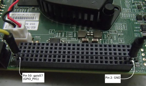 echo 57 > /sys/class/gpio/export
echo out > /sys/class/gpio/gpio57/direction
echo 1 > /sys/class/gpio/gpio57/value
  echo 57 > /sys/class/gpio/export
  echo out > /sys/class/gpio/gpio57/direction
  echo 1 > /sys/class/gpio/gpio57/value
Put a voltmeter on pin 50 (gpio57) of the 2-row header (J3A1) & pin 2 (GND) also of the 2-row header,
You should now see that it is at +1.8V. This pin is LCD_BL_PWM (GPIO_PH1). Setting it to 0:
echo 0 > /sys/class/gpio/gpio57/value
You should now see that it is at 0.0V (roughly).
Once you’re done:
  echo 57 > /sys/class/gpio/unexport
  exit
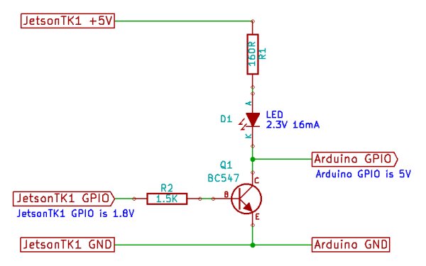 Turning an LED on/off or sending a signal to an Arduino microcontroller from Jetson TK1
You can now set a 1.8V voltage on a GPIO pin, but the GPIO pins on Jetson TK1 don’t have enough electrical current or power to connect directly to an LED and also, 1.8V is a lower voltage than you normally want. So the easiest way to control a single LED from Jetson TK1 is to build a transistor switch circuit, as shown in the circuit diagram (which you can download for the free KiCad package here):
Connect the red wire (+5V) to pin 1 on J3A1 of Jetson TK1 (bottom-right pin of the dual-row header, next to the text saying “DISPLAY TOUCH”) to power the LED from Jetson TK1.
For more detail: Jetson/Tutorials/GPIO
-
How do I set pin GPIO_PH1 as an output?
Use the commands echo 57 > /sys/class/gpio/export followed by echo out > /sys/class/gpio/gpio57/direction. -
What voltage should I see when setting the value to 1?
You should see +1.8V on pin 50 of the J3A1 header relative to pin 2 GND. -
Can I connect an LED directly to the Jetson TK1 GPIO pins?
No, the GPIO pins do not have enough electrical current or power to connect directly to an LED. -
Why is 1.8V considered too low for an LED?
1.8V is lower than the voltage normally required to operate an LED effectively. -
What is the best way to control a single LED from Jetson TK1?
The easiest way is to build a transistor switch circuit. -
Where should I connect the red wire for the LED circuit?
Connect the red wire (+5V) to pin 1 on J3A1 of Jetson TK1. -
How do I unexport the GPIO pin after testing?
Run the command echo 57 > /sys/class/gpio/unexport.
