Summary of 6 Digit LED Clock
The article describes a simple 6-digit LED clock project using six 2.3-inch red 7-segment displays (SA23-12SRWA), a Microchip PIC18F26K20 microcontroller, and a Dallas DS32KHZ temperature-compensated 32.768kHz crystal for accurate timekeeping. The design uses multiplexing for controlling the common-anode displays, requiring one GPIO pin per digit and one per segment, totaling 7 anodes and 8 cathodes. Due to the displays’ high forward voltage (7.4–10V), the anode drivers must handle voltage translation and supply adequate current. The project aims for simplicity and quick completion without complex display drivers.
Parts used in the 6 Digit LED Clock:
- Six 2.3-inch red 7-segment displays (SA23-12SRWA)
- Microchip PIC18F26K20 microcontroller
- Dallas DS32KHZ temperature compensated 32.768kHz crystal
- Prototyping pad board
- Display anode driver components (for voltage translation and current supply)
Recently, I discovered six 2.3-inch red 7 segment displays in my collection that I bought from Rapid Electronics during their clearance of non-RoHS stock. Due to the absence of a clock at my work bench, I opted to create one using prototyping pad board, a Microchip PIC18F26K20 microcontroller, and a Dallas DS32KHZ temperature compensated 32.768kHz crystal.
The displays I used are SA23-12SRWA, which don’t appear to be available from Rapid any more, the closest is SA23-12EWA, however, Farnell and the other usual distributors sell them.
I wanted this to be a fairly quick project to complete, so the schematic is fairly simplistic. The schematic diagram of the clock is shown below:
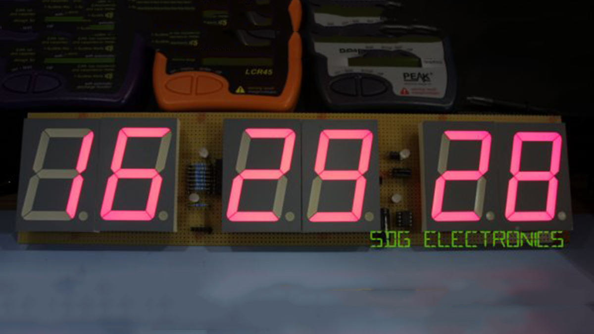
The 7 segment displays are displays with common anodes, featuring segments made up of four red LEDs in a row and decimal points made up of two red LEDs in a row. Different techniques, like multiplexing, shift registers, or dedicated display drivers, can be employed to decrease the amount of GPIO necessary to operate the display. I’ve opted for simple display multiplexing, needing one GPIO for each digit’s common anode and one GPIO for every segment. This results in 7 common anodes and 8 cathodes, with the decimal points and colons linked together. There are numerous techniques available to decrease the required number of GPIOs even more, however, the selected microcontroller has an ample supply of GPIO for this particular task.
The segments have a slightly elevated forward voltage range according to the datasheet, which is indicated to be between 7.4V and 10V. Due to this factor, the anode drivers for the displays need to carry out voltage translation and supply sufficient current for the displays.
FOr More Details: 6 Digit LED Clock