Summary of Working with a Load Cell and an Arduino
This project addresses glass cracking in an air-clamping system by creating a low-cost force measurement setup. It utilizes a compression load cell paired with an instrumentation amplifier to convert minute voltage changes into readable data, processed by an Arduino board for real-time monitoring via serial output. The system calculates force using a linear interpolation formula based on two known calibration loads.
Parts used in the Force Measurement System:
- Eight air-clamping cylinders (McMaster-Carr 62185K64)
- FX 1901 Compression Load Cell
- Burr-Brown INA125 Instrumentation Amplifier
- Arduino board
We built a system that uses eight air-clamping cylinders (McMaster-Carr 62185K64) to push down on a piece of glass to seal it to a sidewall. A number of times, the glass has cracked. So, this project is an attempt to come up with an inexpensive way of measuring how many pounds of force the cylinders are exerting.
The sensor that we want to use is a load cell (an arrangement of strain gauges). The specific load cell that we’re using is the FX 1901 Compression Load Cell. We bought ours from Mouser for $30.
Load cells only make a very small change in voltage, so you have to use an instrumentation amplifier to increase the voltage to something we can use. The specific instrumentation amplifier that we’re using is the Burr-Brown INA125 Instrumentation Amplifier. This also came from Mouser and cost just under $6.
The fastest way to hook everything together and see if it would work was to use an Arduino board and use the computer for readout. These boards can be purchased for around $30.
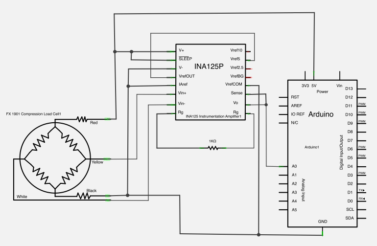
Here is a basic schematic of what we were trying to do.
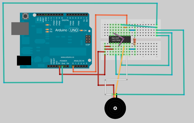
Here is how everything looked hooking up all the parts.
Once everything is hooked up, we just needed to write a program that would read analog pin 0 on the arduino, since that’s where we hooked up the output of the amplifier.
// Arduino with load cell

// Put two known loads on the sensor and take readings. Put those values
// here.
float aReading = 192.0;
float aLoad = 15.0; // lbs.
float bReading = 344.0;
float bLoad = 24.3; // lbs.

long time = 0;
int interval = 500; // Take a reading every 500 ms

void setup() {
  Serial.begin(9600);
}

void loop() {
  float newReading = analogRead(0);

  // Calculate load based on A and B readings above
  float load = ((bLoad - aLoad)/(bReading - aReading)) * (newReading - aReading) + aLoad;

  // millis returns the number of milliseconds since the board started the current program
  if(millis() > time + interval) {
    Serial.print("Reading: ");
    Serial.print(newReading,1); // 1 decimal place
    Serial.print("  Load: ");
    Serial.println(load,1);  // 1 decimal place, println adds a carriage return
    time = millis();
  }
}
For more detail: Working with a Load Cell and an Arduino
- Why was this system built?
To find an inexpensive way of measuring how many pounds of force the cylinders are exerting because the glass has cracked multiple times. - What specific load cell is used in the project?
The FX 1901 Compression Load Cell, which costs $30 and was bought from Mouser. - How does the system handle small voltage changes from the sensor?
An instrumentation amplifier, specifically the Burr-Brown INA125, is used to increase the voltage to something usable. - What component is used for the readout and processing?
An Arduino board is used to hook everything together quickly and provide computer readout. - Which analog pin is used to read the amplifier output?
Analog pin 0 on the Arduino is used to read the output of the amplifier. - How often does the program take a reading?
The interval is set to 500 ms, meaning it takes a reading every half second. - What method is used to calculate the load value?
The code uses a linear calculation based on two known loads and their corresponding readings to determine the current load.