Summary of Wireless Altoids Display using an Arduino
This Instructable shows how to convert Altoids tins into a compact wireless 2x16 character display using Arduino and XBee modules (or a USB-only alternative). One tin holds an Arduino, LCD and XBee; a second tin holds an XBee connected to a PC. Steps include preparing the tin, sanding, drilling holes for the LCD, antenna and wire pass-through, and assembling components for a portable notification or data-logging display.
Parts used in the Wireless Altoids Display:
- ALTOIDS TIN (2x for P2P setup; 1x for USB-only)
- Arduino Duemilanove
- 2x16 LCD HD44780
- Hex posts/spacers (4x)
- Matching screws (4x)
- Sheet insulation (card or foam)
- XBee modules with U.FL antenna connector (2x for P2P)
- U.FL to RP-SMA cable connector (2x)
- Adafruit XBee adapter kit (2x)
- RP-SMA 2.4GHz duck antenna (2x)
- USB type A to type B cable (1x)
- USB to serial FTDI cable (1x)
- Cat5 cable
This Instructable will show you how to modify an Altoids tin for a wireless 2×16 character display.
Using an Altoids tin was inspired by the need to have a small yet protective enclosure for a pair of Xbee modules recently bought from Sparkfun. I purchased the Xbee Pro modules with external antenna for the extended range the setup provides (useful for future projects). Then I realised I would need to mount the antenna socket and have a box to house the circuits.
A L T O I D S !
Overall Configuration
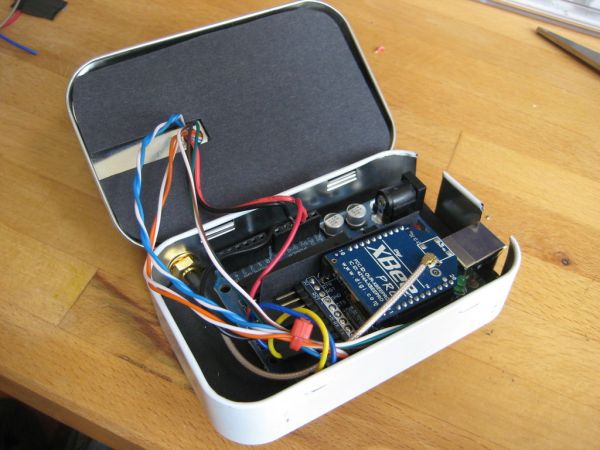
There will be a ‘remote’ Altoids tin containing Arduino, LCD and Xbee module.
A second Altoids tin containing an Xbee module only. This connects to the PC with a USB to FTDI serial cable.
Data is sent from the PC using a terminal program such as the Arduino ‘Serial Monitor’ and appears on the Altoids display.
So here are some possible ideas for use with this setup:

(Data flow PC to Wireless Display)
– Email Notifier
– RSS Feeds
– Facebook/Twitter Updates
– Realtime Clock
(Data flow Wireless Display to PC)
– Weather Station
– Speedometer
– Engine Monitoring
– Heart Rate Monitor
– Other realtime data logging
Let’s get started!
Step 1: Components & Tools
So here’s a list of what you’re going to need for this project:
– – – – – – – – – – – – – – – – – – – – – – – – – – – – – – – – – – – – –
A) Featured P2P Wireless Setup
– (2x) ALTOIDS TIN
– (1x) Arduino Duemilanove
– (1x) 2×16 LCD HD44780
– (4x) Hex Posts/Spacers
– (4x) Matching Screws
– Form of sheet insulation (Card / Foam etc.)
– (2x) Xbee Modules (U.FL antenna connector)
– (2x) U.FL to RP-SMA cable connector
– (2x) Adafruit Industries Xbee Adapter Kit
– (2x) RP-SMA 2.4Ghz Duck Antenna
– (1x) USB type A to type B
– (1x) USB to serial FTDI
– Cat5 Cable
– – – – – – – – – – – – – – – – – – – – – – – – – – – – – – – – – – – – –
I realise that the Xbee modules can be quite costly.
If you still want wireless and you’re content with one-way communication then there are alternative radio modules such as these from HopeRF:
http://shop.jeelabs.com/products/rfm12b
I think it’s worth mentioning that this project can still be effective without wireless communication so why not create a neat USB desktop widget?
B) USB Version Only
If you just want to create a USB Altoids Message Display you’re going to need:
– (1x) ALTOIDS TIN
– (1x) Arduino Duemilanove
– (1x) 2×16 LCD HD44780
– (4x) Hex Posts
– (4x) Matching screws
– (1x) USB type A to type B
– Cat5 Cable
– Form of sheet insulation (Card / Foam etc.)
– – – – – – – – – – – – – – – – – – – – – – – – – – – – – – – – – – – – –
Tools Needed
– Soldering iron & solder
– Needle-nose pliers
– Scissors
– Tin snips
– Marker pen
– Wire strippers
– Cross head screwdriver
– Fine grade sandpaper
– Drill & bits 3mm + 6.5mm
Step 2: Prepare the surface…
As iconic as the Altoids graphics are, I found that I quite liked the ‘brushed’ metal look.
Take some sandpaper and begin wearing away the top layer of paint.
(The finer the grade of sandpaper, the smoother the finish)
Step 3: Mark & drill holes
You will need to mark out and drill 6x holes in total.
1. Place the the LCD over the top surface and mark 4x holes (3mm)
Alternatively you could create a cardboard template to be more accurate.
2. Use a larger, 6mm drill for the antenna socket.
I chose to mount the socket on the back left on the tin as this would allow the antenna to be folded down parallel to the case for storage.
3. The final 6mm hole (underneath display) will allow the wires from the LCD to pass through to the inside.
NOTE: Be patient when drilling these holes through the metal. I found that the best solution was to use a combination of a high speed setting and slow movement into the material. If you’re too quick, you can easily deform the metal.
– (1x) Arduino Duemilanove
– (1x) 2×16 LCD HD44780
– (4x) Hex Posts/Spacers
– (4x) Matching Screws
For more detail: Wireless Altoids Display using an Arduino
- What is the overall configuration of the wireless Altoids display project?
A remote Altoids tin contains Arduino, LCD and XBee; a second tin contains an XBee connected to the PC via USB to FTDI, sending data from PC to the display. - What components are needed for the featured P2P wireless setup?
The article lists 2 Altoids tins, Arduino Duemilanove, 2x16 LCD HD44780, 4 hex posts, 4 matching screws, sheet insulation, 2 XBee modules with U.FL, 2 U.FL to RP-SMA cables, 2 Adafruit XBee adapter kits, 2 RP-SMA duck antennas, USB A to B, USB to serial FTDI, and Cat5 cable. - What can the wireless display be used for?
Suggested uses include email notifier, RSS feeds, Facebook/Twitter updates, realtime clock, and sensor data like weather station or heart rate monitor. - Can this project be built without wireless communication?
Yes, the article notes a USB-only version is possible and lists the parts needed for USB-only configuration. - What alternative radio modules are suggested if XBee modules are too costly?
The article suggests one-way radio modules such as the HopeRF RFM12B as an alternative. - How many holes and of what sizes need to be drilled in the tin?
Drill six holes in total: four 3mm holes for mounting the LCD and two 6mm holes (one for the antenna socket and one for wire pass-through under the display). - Where is the antenna socket mounted on the tin?
The author mounted the antenna socket on the back left of the tin so the antenna can fold down parallel to the case for storage. - What surface preparation is recommended for the Altoids tin?
Use sandpaper to wear away the top paint layer for a brushed metal look; finer sandpaper gives a smoother finish. - What tools are required for assembling the project?
Required tools include a soldering iron and solder, needle-nose pliers, scissors, tin snips, marker pen, wire strippers, cross head screwdriver, fine sandpaper, and drills with 3mm and 6.5mm bits.