Introduction
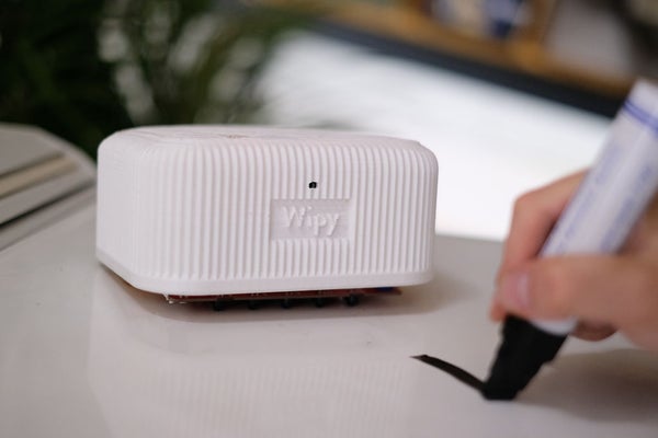
Did you ever get tired of cleaning the whiteboard? Have you ever wondered how much your life would improve if a robot could do this for you? You now have the chance to make this a reality with Wipy: the overly motivated whiteboard cleaner. Wipy will properly clean your embarrassingly bad drawings, and it will even do it with a cute smile. You don’t even need to activate it! It will just clean the board when you least expect it… Uhhh…*cough cough*…we, of course, mean: when you need it most!
Features:
– Our future friend will be able to stick to the board using magnets and is able to move through space using grippy wheels.
– It will be able to follow a line and erase it using a line-following sensor and a sponge.
– Wipy has the ability to measure the distance to your hand using a time-of-flight sensor.
– We will give Wipy a cute personality using a small OLED screen.
The project was conducted as part of the Computational Design
and Digital Fabrication seminar in the ITECH masters program.
Lasath Siriwardena, Simon Lut & Tim Stark
Step 1: Wipy’s Logic
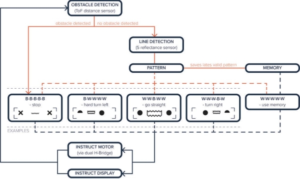
Wipy works based on the interplay between the line sensor and the Time of flight sensor. Depending on what kind of line it detects and how close your hand is, Wipy react in a number of ways as seen in the diagram.
Step 2: Components and Theory
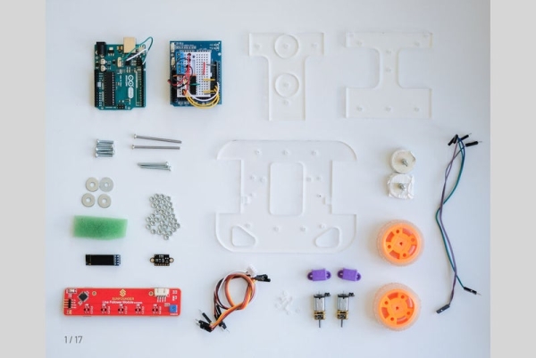
To re-create this amazing piece of advanced wiping technology you will need the following items:
Components
To create the chassis of the robot, you’ll need access to a laser cutter. For the case, a 3d printer was used.
The base plate elements were all cut from a 500 x 250 x 4 mm sheet of Plexiglas.
We also suggest that you get an Arduino Kit which will included many of the fundamental components for this project (Amazon)
Base & Case
1 x 3D Printed Case
1 x Top base plate (Lasercut)
1 x Middle base plate (Lasercut)
1 x Bottom base plate (Lasercut)
36 x M3 Nuts
5 x M3 Bolts 15 mm
4 x M3 Bolts 30 mm
2 x Magnets (we got them here)
Main Electronics
1 x Arduino Uno R3 or generic equivalent – (Amazon)
1 x Arduino Expansion Shield (Included in starter kit)
1 x Mini Breadboard (Included in starter kit)
19 x Jumper wires (Included in starter kit)
11 x[OPTIONAL EXTRA] Solderless Jumper wires – (Amazon)
1 x Power bank with minimum 2 USB slots – (Amazon). Avoid cheap power banks as the power source can be unreliable.
1 Spool x CCA twin wire for connecting power bank to Arduino & Motors – (Amazon)
1 x Screw Terminal Blocks – (Amazon)
Sensors & Motors
1 x Micro-motors, Wheel Kit & Bracket Kit – (Pimoroni)
1 x[OPTIONAL SPARE] Motor Brackets 3D Print File – (Thingiverse)
1 x 0.91″ OLED Screen – (Amazon
1 x L293D Motor Driver IC – (Amazon)
1 x 5 Channel IR Line Tracking Sensor – (Amazon)
1 x Time of Flight Sensor (VL53L0X) – (Amazon)
Tools
– Phillips head screwdriver
– Flat head screwdriver
– Craft Knife
– Duct Tape
Theory
Line Tracking sensor
An array of five IR sensors is used in the linesensor. These IR-sensor’s are able to pick able to pick up color. The sensor has an emitter and a receiver. The emitter is able to shoot infrared waves, if a surface is very reflective (like a white surface), it while reflect more of the waves back in the IR receiver. If the surface absorbs radiation, like a black color, the IR receiver will receive less radiation. To follow the line at least two sensors are needed.
Motors
To control the DC Motor’s, you’ll need a type of driver to control them. The I2C L293D Motor Driver IC The L293D is a motor driver that is a cheap and relatively simple way to control both the speed and direction of spin of two DC motors. For a more indepth information about the L293D, Lastminuteengineers has a fantastic overview: https://lastminuteengineers.com/l293d-dc-motor-ar…
Time-of-flight sensor:
This sensor is able to measure distance using a principle that is already conveniently stated in the title of the sensor: time of flight. It is a very accurate sensor and can be found in for example drones or LiDAR systems. It is able to shoot a laser into a certain direction and measure the time it takes for the laser to return, from that, the distance can be calculated.
Step 3: Preparing Base Case
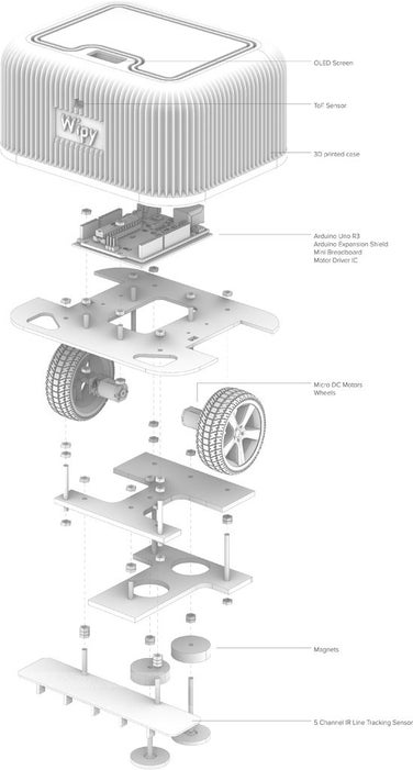
Wipy’s body comes in two parts; a laser-cut base and a 3d printed case.
1. For the base, it can be laser cut or hand cut depending on the material. Please find the file attached in the components section. We suggest using strong but lightweight materials such as acrylic sheets (3 – 4 mm) or plywood (2.5 – 3 mm). During our prototyping phase, we used10mm foam core which worked particularly well and the current design should work with it (some fine tuning will be needed). Foam-core is also easy to cut by hand for people without access to laser cutters.
2. The case was printed with PLA with a layer height of 0.2 mm and an infill density of 25%. We also suggest a wall thickness of 0.8mm.
Step 4: Assembling the Electronics: Motor Driver & I2C
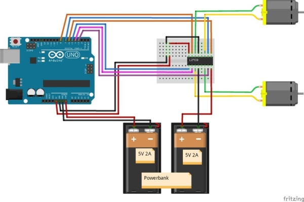
In assembling the electronics we are first going to start with the L293D Motor Driver.
- Stick the mini-breadboard to the Arduino extension shield.
- Place the L293D on the very end of the mini breadboard (where the little plastic connection piece sticks out on the short side). Note, the full circle on top of the L293D should be at the end of the board.
- Connect all the solder-less jumper wires first
- Attach the remaining wires to the Arduino and subsequently to the motors. It does not matter if you confuse the order of the wires for your motors, as you’ll find out once your motor is turning the wrong way.
- Load the sample code of the motors to the Arduino to test them – it can be found at the bottom of this page: (sample code Motors)
Step 5: Assembling the Base
To assemble the base, we suggest the following order.
- First, connect the motors to the top base using the brackets. The brackets use M2 nuts and bolts. Carefully take your time screwing the bolts in as they are quite small and fiddly.
- Connect the Arduino to the top plate, make sure that the Arduino is detached from its bracket. Use M2 bolts to connect it. If M2 bolts are not in your possession, you can also use M3, but it takes a bit more brute force.
- Next: attach bolts to the magnets, slide the bottom plate over the bolts and attach the bolts to the middle plate at the indicated locations. Now attach the middle and bottom plate.
- Attach the line sensor to the middle plate using the indicated bolts. Make sure to also put the neighboring bolts in the middle plate, as the holes are not accessible anymore when the line sensor is attached.
- Add all bolts in the middle plate that connect to the top base.
- Finally, place and tighten the top base plate to the rest of the base.
Source: Wipy: the Overly Motivated Whiteboard Cleaner