Summary of VU Meter – LED Noise-o-Meter for Classrooms
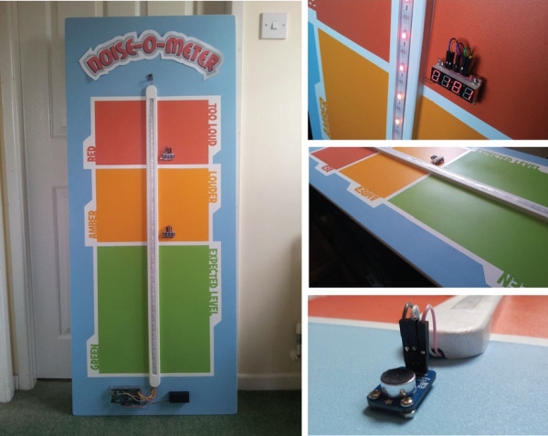
This project is a dynamic, technology-enhanced noise meter designed for primary classrooms. Combining audio sensing with visual feedback, it functions as both a VU meter and a behavior zone board. Using an Arduino, microphone amplifier, and NeoPixel LEDs, the device displays "Expected," "Louder," or "Too Loud" levels via color-coded zones (Green, Amber, Red). Optional 7-segment displays track peak noise levels. The build involves custom MDF casing, precise wiring, and stencil-based painting to create a professional educational tool that responds in real-time to classroom volume.
Parts used in the Classroom Noise-o-Meter:
- MDF sheet wood
- Adafruit Digital NeoPixel LED Strip (1 metre)
- Arduino Mega/Uno
- Adafruit Electret Microphone Amplifier
- Screws
- Jumper wires
- 9V battery holder
- Sparkfun Serial 7-Segment Display – RED (optional)
- Sparkfun Serial 7-Segment Display – YELLOW (optional)
- Right angled break away headers
- M3 stand-off
- Frisket Matt Low Tack Masking Film
- White paint
- Spray paint x4
- Transparent Arduino Mega case
- Masking paper and tape
I built this a short while ago as an idea to use in a primary classroom setting. Poster displays are often used by primary teachers wanting to control the noise levels in their classrooms but I wanted to add technology to make it dynamic and responsive. The motivation for this came after seeing the Adafruit Digital NeoPixel LED Strip online and realising its potential as part of a VU meter. Everything else developed from this.
Things I used:
- MDF (sheet wood)
- Adafruit Digital NeoPixel LED Strip (1metre)
- Arduino Mega/Uno (In the images you see UNO, but that’s because the Mega hadn’t arrived at this point – I needed the Mega for more 5V and Ground pins)
- Adafruit Electret Microphone Amplifier
- Screws
- Jumper wires
- 9V battery holder
- Sparkfun Serial 7-Segment Display – RED (optional) Sparkfun Serial 7-Segment Display – YELLOW (optional)
- Right angled break away headers M3 stand-off
For the painting
- Frisket Matt Low Tack Masking Film
- White paint – to act as an undercoat
- Spray paint x4 (the 4 colours used)
- Transparent Arduino Mega case
- Masking paper and tape
Step 1: Design and Build
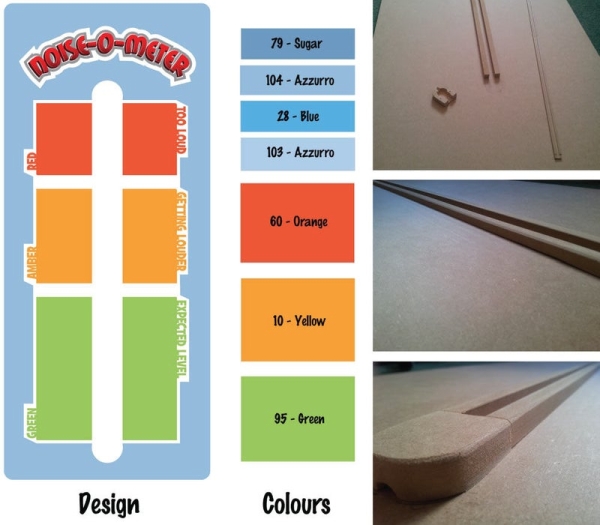
I bought a large sheet (1830mm x 610mm x 12mm thick) of MDF (Medium Density Fibreboard) from a hardware store and got them to cut two thin batons off one side (approx. 1cm wide) – they offered a cutting service and as these are thin batons it made sense to have an industrial-size precision saw make the cuts instead of struggling with it at home. The batons will form a channel to feed the LED strip down and to hide all the wires behind. My channel is roughly 90cm long which accommodates 32 LEDs.
I positioned the channel somewhere in the middle of the MDF sheet, then cut the surplus parts from the top and bottom being mindful of what additional components I needed to accommodate on the board (see design picture). Using the surplus MDF I fashioned two ends for the channel, hollowing it out from behind, again to fit the wires behind.
Step 2: Fixing Together and Initial Test
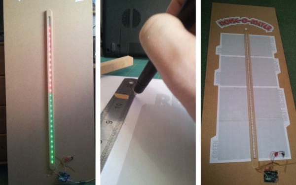
Once happy I fixed the batons and end pieces in place from behind with screws then wired the LED strip and Adafruit Electret Microphone Amplifier to an Arduino UNO (again, later I use a MEGA but at this testing stage I only had a UNO to hand). The process for attaching this altogether and running the code is very well documented by user erin_cuneo in this instructable so I refer you there for now.
As I intented this to be used in classrooms I had to decide how to divide the meter levels, so opted for Expected, Louder and Too Loud. It occurred to me when designing this that each of these could correspond to Red, Amber and Green (typical VU meter colours in audio equipment). These colours are also often used in schools for zone boards – to monitor good and bad behaviour (green, good – red, bad) so I decided to couple the two – making this dual purpose – VU meter and zone board.
I used an Adobe Illustrator and an A3 printer to create, what will later be, the stencils and fixed them temporarily in place on the board making sure the desired number of LEDs per zone/level were contained by each stencil.
Step 3: Adding Some Counter Displays
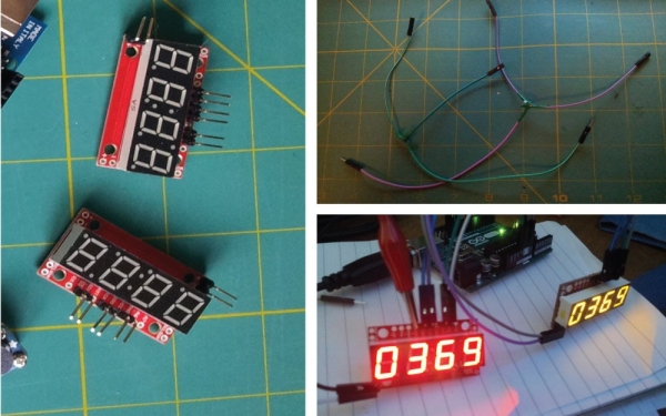
You can stop at Step Two, just position and fix everything in place as desired, however I saw the Sparkfun Serial 7-Segment Display and wondered whether I could incorporate this into the project as a way to track where the levels had peaked (in which zone). I could have opted for Adafruit displays but the Sparkfun tutorials here seemed easier to follow. Listed in the ‘things I used’ at the top of this instructable are right-angled headers, this is because the displays came unsoldered and the right-angled ones would sit better on the board – so I proceeded to solder these in place.
I followed the SPI method explained in the Sparkfun tutorial which required me to splice wires to connect the two SCK and SDI pins together. I then used an example ‘cycles’ program and adapted it to my needs. I attach some example code below (example_counter_code.ino), detailed in the code are the pins I connected to.
Read more: VU Meter – LED Noise-o-Meter for Classrooms
- What is the main purpose of this project?
The project serves as a dynamic noise meter for primary classrooms that acts as both a VU meter and a zone board. - How are the noise levels divided?
The meter divides levels into three categories: Expected, Louder, and Too Loud. - Which colors correspond to the noise levels?
The system uses Green for Expected, Amber for Louder, and Red for Too Loud. - Can the device track peak noise levels?
Yes, optional Sparkfun Serial 7-Segment Displays can be added to track where the noise levels peaked. - Why was the MDF cut into batons?
The batons form a channel to feed the LED strip down and hide all the wires behind the display. - Does the design require specific soldering techniques?
Yes, right-angled break away headers are used because the displays came unsoldered and need to sit better on the board. - How were the stencils created for the paint job?
An Adobe Illustrator design printed on an A3 printer was used to create the stencils for the zones. - What microcontroller was initially used for testing?
An Arduino UNO was used for the initial testing stage before switching to a Mega for more power pins.