Summary of Using a transistor to control high current loads with an Arduino
In this tutorial you learn to use an NPN transistor (TIP120) as an electronic switch to control high-current DC loads (motors or incandescent lights) from a microcontroller. The transistor's base connects to a microcontroller output, the emitter to ground, and the collector to the load, which is powered by a separate supply. Grounds of both supplies must be common. IRF510/IRF520 MOSFETs are offered as alternatives with higher ratings and greater static sensitivity.
Parts used in the TIP120 transistor motor control project:
- Microcontroller (e.g., Arduino)
- TIP120 NPN transistor
- DC motor or incandescent light (high-current load)
- Separate power supply for the motor (e.g., 9V battery, 4xAA pack, 12V wall wart)
- Breadboard
- Connecting wires
- Common ground connection between motor supply and microcontroller
In this tutorial, you’ll learn how to control a high-current DC load such as a DC motor or an incandescent light from a microcontroller.
(:toc Table of Contents:)
Connect a transistor to the microcontroller
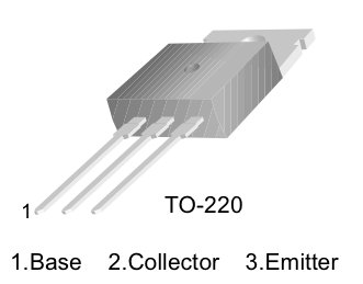
The transistor allows you to control a circuit that’s carrying higher current and voltage from the microcontroller. It acts as an electronic switch. The one you’re using for this lab is an NPN-type transistor called a TIP120. The datasheet for it can be found here. It’s designed for switching high-current loads. It has three connections, the base, the collector, and the emitter. The base is connected to the microcontroller’s output. The high-current load (i.e. the motor or light) is attached to its power source, and then to the collector of the transistor. The emitter of the transistor is connected to ground.
Pinout of a TIP-120 transistor, from left to right: base, collector, emitter.
Note: you can also use an IRF510 or IRF520 MOSFET transistor for this. They have the same pin configuration as the TIP120, and perform similarly. They can handle more amperage and voltage, but are more sensitive to static electricity damage.
The schematic symbol of an NPN transistor where B is the base, C is the collector, and E is the emitter.
Connect the base to an output pin of the microcontroller, and the emitter to ground like so:
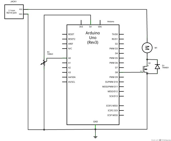
Connect a motor and power supply
Attach a DC motor to the collector of the transistor. Most motors will require more amperage than the microcontroller can supply, so you will need to add a separate power supply as well. If your motor runs on around 9V, you could use a 9V battery. A 5V motor might run on 4 AA batteries. a 12V battery may need a 12V wall wart, or a 12V battery. The ground of the motor power supply should connect to the ground of the microcontroller, on the breadboard.
For more details: Uing a transistor to control high current loads with an Arduino
- How do I connect the TIP120 transistor to a microcontroller?
Connect the base to a microcontroller output pin, the emitter to ground, and the collector to the motor/load. - Can I drive a motor directly from the microcontroller?
No; most motors require more current than the microcontroller can supply, so use a transistor and a separate power supply. - What power supply should I use for a 9V motor?
You can use a 9V battery as the motor power supply. - Do the grounds need to be connected between supplies?
Yes; the ground of the motor power supply should connect to the ground of the microcontroller. - Can I use a MOSFET instead of a TIP120?
Yes; IRF510 or IRF520 MOSFETs can be used as alternatives and can handle more amperage and voltage. - Are there any cautions when using MOSFETs?
Yes; MOSFETs like IRF510/IRF520 are more sensitive to static electricity damage. - Where does the motor connect in the circuit?
Attach the motor between its power supply positive and the collector of the transistor. - What are the three pins of the TIP120?
From left to right the pins are base, collector, emitter.