Summary of Using Servos with Arduino made easy !
This article explains how to control a servo motor's precise rotation using an Arduino. By reading analog values from a potentiometer, the system maps input data to specific angles, allowing for intuitive manual control of the servo shaft via Pulse Width Modulation (PWM) signals generated by the microcontroller.
Parts used in the Servo Control Project:
- Servo
- Arduino
- Jumper wires (male to male)
- 10k potentiometer
- USB cable
- Protoboard or breadboard
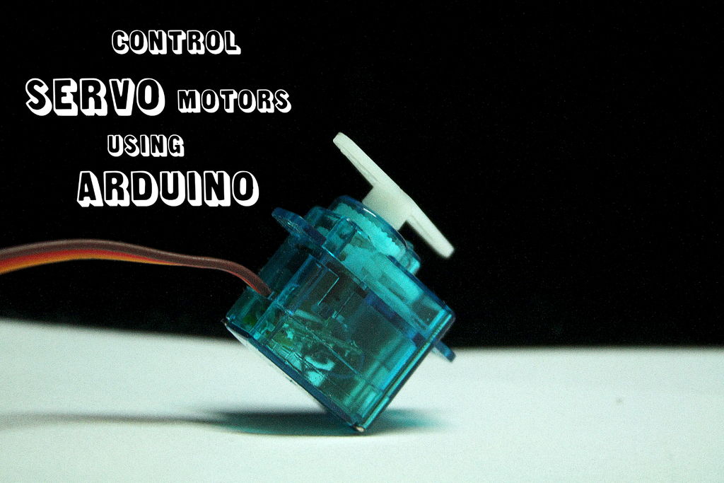
Servomotors or simply servos are essential components of a robot which convert electrical energy into mechanical energy.They are widely used in the field of RC hobby and robotics. But unlike simple geared motors , these servos are made by integrating a geared motor with a position feedback circuit which allows us to control the rotation of the shaft precisely. To drive a servo , we need a controller which provides PWM signals to the servo which in turn determines the angle of rotation. Using an arduino to do this is pretty easy job, all you need is :
1. A servo ( To make your own servo , check this out : make your own servo ! )
2. Arduino ( and the default “knob.ino” sketch )
3. A bunch of jumper wires ( male to male )
4. A 10k potentiometer
5. A USB cable
Step 1: Prepare the potentiometer
The potentiometer has three pins one is for the wiper and the other two have 10k resistance between them. The wiper should be connected to the analog 0 pin on the arduino , one of the remaining two pins should be connected to +5v and the other should be grounded. The potentiometer has been soldered on a protoboard to make it “arduino friendly” ( you can use a breadboard too ).
Based on how you rotate the the wiper arm , the analog values on the analog 0 pin will change and therefore the angle of rotation of the servo will also change.
Step 2: Upload the program and attach the servo
I’ve made some minor changes in the program :
pin 15 ( analog 1 ) and pin 16 ( analog 2 ) are used as power source for the potentiometer board.
The arduino reads values from potentiometer between 0 and 1023
” val = analogRead(potpin); “
Then it converts or “maps” the values from 0-1023 to 0-179 ( in degrees )
” val = map(val , 0 , 1023 , 0 , 179 ); “
Finally , it writes these values to the servo.
CONNECTIONS :
1. Connect the potentiometer to the arduino ( as mentioned above )
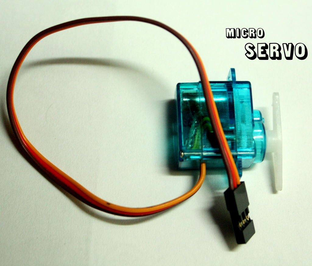
2. Attach the yellow/orange signal pin of servo to pin 9 on arduino.
3. Connect the red wire to VIN pin* and the brown one to ground.
4. Take power from USB.
5. Upload the attached sketch to arduino.
***IF you are using external power source ( other than USB ) then first convert the voltage to 5v.
>> some important tips
For more detail: Using Servos with Arduino made easy !
- What is the main function of a servo compared to simple geared motors?
Servos integrate a geared motor with a position feedback circuit to allow precise control of the shaft rotation. - How does the controller determine the angle of rotation?
The controller provides PWM signals which determine the angle of rotation for the servo. - Which pin on the Arduino should the potentiometer wiper connect to?
The wiper should be connected to the analog 0 pin on the Arduino. - What range of values does the Arduino read from the potentiometer?
The Arduino reads values from the potentiometer between 0 and 1023. - How are the raw values converted for the servo?
The program maps the values from 0-1023 to 0-179 degrees. - Which Arduino pin connects to the servo signal wire?
The yellow or orange signal pin of the servo attaches to pin 9 on the Arduino. - What power source options are mentioned for the project?
You can use power from USB or an external source converted to 5v. - Can I use a breadboard instead of a protoboard?
Yes, you can use a breadboard instead of a protoboard for the connections.