Summary of Using Servo Motors with Arduino
This article explains the fundamentals of servo motors, detailing their operation via PWM signals from microcontrollers or 555 timers. It guides users through testing a servo with an Arduino using the "Sweep" example and controlling it manually with a potentiometer via the "Knob" code. The guide covers wiring connections for power, ground, and signal pins, emphasizing the standard 0 to 180-degree movement range suitable for robotics and animatronics.
Parts used in the Servo Motor Project:
- Servo motor
- Arduino board
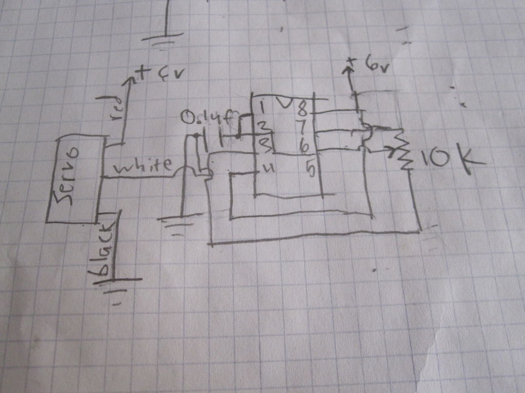
- 555 timing IC
- Potentiometer (10k to 100k)
- Male header pins
- Female jack connectors
- Solid core wires
Step 1: What is a Servo motor
Step 2: Testing the servo
the first thing that you should do is make sure your servo motor is working. because the servos wires end in a female header, you cannot plug it into the arduino (unless you have a shield. insert solid core wires into the headers, so you can attach it to the pins of the arduino (or anything else). When you downloaded your programming environment for arduino, it should have two examples for the servo. The one we are going to use first is called sweep. Go to the “open” icon next to save near the top of the window on the environment. click on it, and a list of files should come up. go down to the one that says servo, and put your mouse over it. two files should come out of it. one called “sweep” and one called “knob”. click on the one called sweep, compile the code and upload it to your board. if everything is connected correctly, the servo should begin to go back and forth from 0 to 180 degrees. If you cannot find the code, copy this:
// Sweep
// by BARRAGAN <http://barraganstudio.com>
// This example code is in the public domain.

#include <Servo.h>

Servo myservo;  // create servo object to control a servo
// a maximum of eight servo objects can be created

int pos = 0;    // variable to store the servo position

void setup()
{
myservo.attach(9);  // attaches the servo on pin 9 to the servo object
}

void loop()
{
for(pos = 0; pos < 180; pos += 1)  // goes from 0 degrees to 180 degrees
{                                  // in steps of 1 degree
myservo.write(pos);              // tell servo to go to position in variable 'pos'
delay(15);                       // waits 15ms for the servo to reach the position
}
for(pos = 180; pos>=1; pos-=1)     // goes from 180 degrees to 0 degrees
{
myservo.write(pos);              // tell servo to go to position in variable 'pos'
delay(15);                       // waits 15ms for the servo to reach the position
}
}
be sure to plug in the white wire to digital pin 9, the black wire to one of the ground pins on arduino, and the red wire to the 5v pin on the arduino board.
Step 3: New code
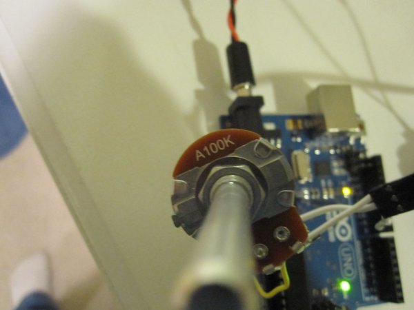
Now that you know your servo works, you can begin to incorporate sensors into the mix. the first thing you should do is use a potentiometer. Use anything between 10 and 100k. keep the servo attached as it was using the sweep example. attach the top pin on the pot to 3.3v on the arduino. Connect the bottom pin to ground on the board. Connect the center of wiper pin of the pot to A0 (the first analog pin) on arduino. go to “open” on the IDE again. Go to servo and open “Knob”. compile the code and upload it to your board. When the program is running you will be able to control the position of the servo with a potentiometer. If you cannot find the code, copy this:
// Controlling a servo position using a potentiometer (variable resistor)
// by Michal Rinott <http://people.interaction-ivrea.it/m.rinott>

#include <Servo.h>

Servo myservo;  // create servo object to control a servo

int potpin = 0;  // analog pin used to connect the potentiometer
int val;    // variable to read the value from the analog pin

void setup()
{
myservo.attach(9);  // attaches the servo on pin 9 to the servo object
}

void loop()
{
val = analogRead(potpin);            // reads the value of the potentiometer (value between 0 and 1023)
val = map(val, 0, 1023, 0, 179);     // scale it to use it with the servo (value between 0 and 180)
myservo.write(val);                  // sets the servo position according to the scaled value
delay(15);                           // waits for the servo to get there
}
For more detail: Using Servo Motors with Arduino
- How does a servo motor determine its position?
A servo motor uses pulse width modulation (pwm) from a microcontroller or a 555 timing IC to know what position to move its horn to. - Can a servo motor rotate continuously like a conventional electric motor?
No, most servos do not move in continuous rotations; the standard servo moves anywhere between 0 and 180 degrees. - What are the functions of the three servo wires?
The black wire connects to ground, the red wire connects to the positive power supply, and the white or yellow wire receives the pwm signal. - How can I test if my servo motor is working correctly?
You can upload the Sweep example code from the Arduino environment to make the servo go back and forth from 0 to 180 degrees. - Which digital pin should I use for the servo signal wire?
The article specifies plugging the white wire into digital pin 9 on the Arduino board. - How do I control the servo position manually?
You can connect a potentiometer to analog pin A0 and upload the Knob example code to control the servo position. - What resistance range is recommended for the potentiometer?
Any value between 10 and 100k ohms can be used for the potentiometer. - What voltage should be connected to the top pin of the potentiometer?
The top pin on the pot should be connected to 3.3v on the Arduino.