Summary of Using ESP-01 and Arduino UNO
This tutorial demonstrates integrating an ESP8266 ESP-01 module with an Arduino UNO to enable Wi-Fi connectivity, allowing the Arduino to control an LED remotely and report button presses. The project establishes serial communication between the microcontrollers, configures the ESP as a server, and uses AT commands to manage network interactions and data transmission.
Parts used in the ESP-01 and Arduino UNO Wi-Fi Project:
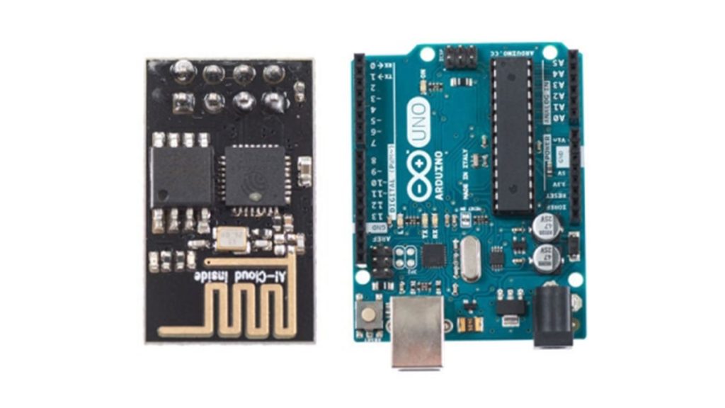
- ESP8266 ESP-01
- Arduino UNO
- Jumper Wires
- Push Button
- LED
- 330Ω Resistors (x2)
In our previous tutorial, we learned how to set up the ESP8266 ESP-01 and establish communication with other devices.
In this tutorial we are going to show how to use the ESP-01 module to give the Arduino UNO access to a Wi-Fi network and interact with inputs and outputs.
Step 1: Materials
The materials that you will need for this tutorial are:
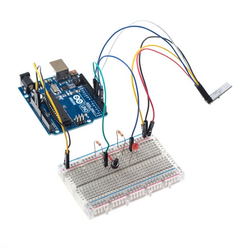
Add the LED and button to the wiring setup from the previous tutorial as shown in the images above.
Note that TX and RX from the ESP-01 are now connected to pins 7 and 6 correspondingly.
Step 2: Coding
Now that we have the setup complete, we are going to control the LED via Wi-Fi to turn it ON or OFF.
We are also going to check to make sure that when the button is pressed that a message is received about its change of state.
The following code shows how to do this:
#include
//#include
#define TIMEOUT 5000 // mS
#define LED 5
SoftwareSerial mySerial(7, 6); // RX, TX
const int button = 11;
int button_state = 0;

void setup()
{
 pinMode(LED,OUTPUT);
 pinMode(button,INPUT);
 Serial.begin(9600);
 mySerial.begin(9600);
 SendCommand("AT+RST", "Ready");
 delay(5000);
 SendCommand("AT+CWMODE=1","OK");
 SendCommand("AT+CIFSR", "OK");
 SendCommand("AT+CIPMUX=1","OK");
 SendCommand("AT+CIPSERVER=1,80","OK");
}

void loop(){
 button_state = digitalRead(button);

 if(button_state == HIGH){
    mySerial.println("AT+CIPSEND=0,23");
    mySerial.println("Button was pressed!");
    delay(1000);
    SendCommand("AT+CIPCLOSE=0","OK");
  }

 String IncomingString="";
 boolean StringReady = false;

 while (mySerial.available()){
   IncomingString=mySerial.readString();
   StringReady= true;
  }

  if (StringReady){
    Serial.println("Received String: " + IncomingString);

  if (IncomingString.indexOf("LED=ON") != -1) {
    digitalWrite(LED,HIGH);
   }

  if (IncomingString.indexOf("LED=OFF") != -1) {
    digitalWrite(LED,LOW);
   }
  }
 }

boolean SendCommand(String cmd, String ack){
  mySerial.println(cmd); // Send "AT+" command to module
  if (!echoFind(ack)) // timed out waiting for ack string
    return true; // ack blank or ack found
}

boolean echoFind(String keyword){
 byte current_char = 0;
 byte keyword_length = keyword.length();
 long deadline = millis() + TIMEOUT;
 while(millis() < deadline){
  if (mySerial.available()){
    char ch = mySerial.read();
    Serial.write(ch);
    if (ch == keyword[current_char])
      if (++current_char == keyword_length){
       Serial.println();
       return true;
    }
   }
  }
 return false; // Timed out
}
Step 3: Code Explanation
#include <SoftwareSerial.h>
#define TIMEOUT 5000 // mS
#define LED 5
SoftwareSerial mySerial(7, 6); // RX, TX
const int button = 11;
int button_state = 0;
In this part of the code, we include the SoftwareSerial library to allow pins 6 and 7 to receive serial communication from the ESP-01.
We also assign the name “LED” to pin 5 and “button” to pin 11, and make the initial value of the button zero.
Step 4: Code Explanation – Continued
void setup()
{
 pinMode(LED,OUTPUT);
 pinMode(button,INPUT);
 Serial.begin(9600);
 mySerial.begin(9600);
 SendCommand("AT+RST", "Ready");
 delay(5000);
 SendCommand("AT+CWMODE=1","OK");
 SendCommand("AT+CIFSR", "OK");
 SendCommand("AT+CIPMUX=1","OK");
 SendCommand("AT+CIPSERVER=1,80","OK");
}
In the setup, we make the LED an output and the button an input.
We then begin serial communication and define the baud rate for both channels of communication.
Next, we call the function “SendCommand” several times to configure the ESP-01.
With this function you avoid having to open the serial monitor and sending commands manually like we did in the previous tutorial.
First we reset the module and wait for a couple of milliseconds to let it finish.
Then we make it operate in STA mode and ask for the IP address.
Finally, we enable multiple connections and start the server at port 80.
Step 5: Code Explanation – Continued
void loop(){
 button_state = digitalRead(button);

 if(button_state == HIGH){
    mySerial.println("AT+CIPSEND=0,23");
    mySerial.println("<h1>Button was pressed!</h1>");
    delay(1000);
    SendCommand("AT+CIPCLOSE=0","OK");
  }

 String IncomingString="";
 boolean StringReady = false;

 while (mySerial.available()){
   IncomingString=mySerial.readString();
   StringReady= true;
  }

  if (StringReady){
    Serial.println("Received String: " + IncomingString);

  if (IncomingString.indexOf("LED=ON") != -1) {
    digitalWrite(LED,HIGH);
   }

  if (IncomingString.indexOf("LED=OFF") != -1) {
    digitalWrite(LED,LOW);
   }
  }
 }
In the loop, we read the state of the button and assign it to the variable “button_state.”
Then we check if the button is pressed.
If the case is true, we type the command “AT+CIPSEND=0,23” to send 23 bit of data through channel 0 to our device connected to the ESP-01. Then we type the message that we want to send. In this case the message is “Button was pressed!” Note that we can use html formatting to edit the text and make it a header.
Next, we create a string variable that will hold the data coming from the ESP module. Once all data has been read we check if the received data contains either a string equal to “LED=ON” or “LED=OFF” along the lines.
If the first case is true, the LED is turned on. If the second case is true, the LED is turned off.
Read more: Using ESP-01 and Arduino UNO
- How are the TX and RX pins connected?
The TX and RX from the ESP-01 are connected to pins 7 and 6 on the Arduino correspondingly. - What library is included for serial communication?
The SoftwareSerial library is included to allow pins 6 and 7 to receive serial communication from the ESP-01. - Which mode does the ESP-01 operate in?
The code configures the ESP-01 to operate in STA mode using the command AT+CWMODE=1. - At what port does the server start?
The server is enabled at port 80 using the command AT+CIPSERVER=1,80. - How is the button state checked in the code?
The loop reads the button state via digitalRead and checks if the value equals HIGH. - What happens when the button is pressed?
A message stating "Button was pressed!" is sent through channel 0 to the connected device. - Can HTML formatting be used in messages?
Yes, the text can include HTML formatting such as h1 tags to edit the appearance of the text. - How is the LED turned on or off?
The LED turns on if the received string contains "LED=ON" and turns off if it contains "LED=OFF". - What function is used to send AT commands?
The SendCommand function is called repeatedly to configure the ESP-01 without manual input. - What baud rate is used for communication?
Both Serial and mySerial begin communication at a baud rate of 9600.