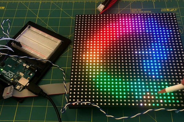
Ordinary digital cameras work by using a large array of light sensors to capture light as it is reflected from an object. In this experiment, I wanted to see whether I could build a backwards camera: instead of having an array of light sensors, I have just a single sensor; but I control each of 1,024 individual light sources in a 32 x 32 LED matrix.
The way it works is that the Arduino illuminates one LED at a time, while using the analog input to monitor changes in the light sensor. This allows the Arduino to test whether the sensor can “see” a particular LED. This process is repeated for each of the 1,024 individual LEDs rapidly to generate a map of visible pixels.
If an object is placed between the LED matrix and the sensor, the Arduino is able to capture the silhouette of that object, which is lit up as a “shadow” once the capture is complete.
BONUS: With minor tweaks, the same code can be used to implement a “digital stylus” for painting on the LED matrix.
Step 1: Parts Used in This Build
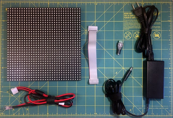
For this project, I used the following components:
- An Arduino Uno with Breadboard
- 32×32 RGB LED matrix (either from AdaFruit or Tindie)
- 5V 4A Power Adapter (from AdaFruit)
- Female DC Power Adapter 2.1mm jack to Screw Terminal block (from AdaFruit)
- A clear, 3mm TIL78 phototransistor
- Jumper wires
AdaFruit also sells an Arduino shield which can be used instead of jumper wires.
As I had some Tindie credits, I got my matrix from Tindie, but the matrix from AdaFruit seems to be identical, so either one should work.
The phototransistor came from my decades old collections of parts. It was a clear 3mm part labeled as a TIL78. As far as I can tell, that part is meant for IR and comes either a clear case or a dark casing that blocks visible light. Since the RGB LED matrix puts out visible light, the clear version must be used.
This TIL78 appears to have been discontinued, but I imagine this project could be made using contemporary phototransistors. If you find something that works, let me know and I will update this Instructable!
Step 2: Wiring Up and Testing the Phototransistor
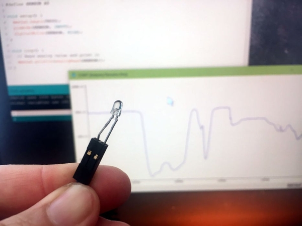
Normally, you would need a resistor in series with the phototransistor across power, but I knew that the Arduino had the ability to enable an internal pull-up resistor on any of the pins. I suspected that I could take advantage of that to hook up the phototransistor to the Arduino without any additional components. It turned out my hunch was correct!
I used wires to connect the phototransistor to the GND and A5 pins on the Arduino. I then created a sketch that set the A5 pin as an INPUT_PULLUP. This is normally done for switches, but in this case it provides power to the phototransistor!
#define SENSOR A5
void setup() {
  Serial.begin(9600);
  pinMode(SENSOR, INPUT_PULLUP);
}
void loop() {
  // Read analog value continuously and print it
  Serial.println(analogRead(SENSOR));
}
This sketch prints values to the serial port corresponding to the ambient brightness. By using the handy “Serial Plotter” from the “Tools” menu of the Arduino IDE, I can get a moving plot of ambient light! As I cover and uncover the phototransistor with my hands, the plot moves up and down. Nice!
This sketch is a nice way to check whether the phototransistor is wired up with the right polarity: the phototransistor will be more sensitive when hooked up one direction versus the other.
Step 3: Wiring Up the Matrix Ribbon Cable to the Arduino
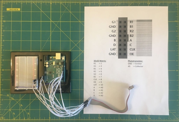
To wire up the matrix to the Arduino, I went through this handy guide from Adafruit. For convenience, I pasted the diagram and pinouts into a document and printed a quick reference page to use while wiring everything up.
Take care to ensure the tab on the connector matches the one in the diagram.
Alternatively, for a cleaner circuit, you could use the RGB matrix shield that AdaFruit sells for these panels. If you use the shield, you will need to solder in a header or wires for the phototransistor.
Step 4: Connecting the Matrix
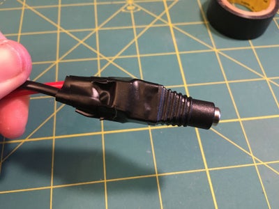
I screwed down the fork terminals on the matrix power leads to the jack adapter, making sure the polarity was correct. Since part of the terminals were left exposed, I wrapped the whole thing up with electrical tape for safety.
Then, I plugged in the power connector and ribbon cable, being careful not to disturb the jumper wires in the process.
Step 5: Install the AdaFruit Matrix Library and Test the Matrix
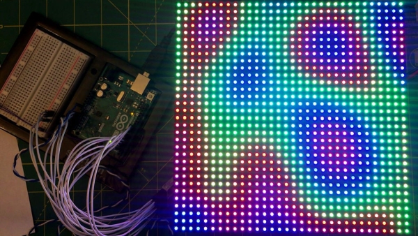
You will need to install the “RGB matrix Panel” and the AdaFruit “Adafruit GFX Library” in your Arduino IDE. If you need help doing this, the tutorial is the best way to go.
I suggest you run some of the examples to make sure your RGB panel works before proceeding. I recommend the “plasma_32x32” example as it is quite awesome!
Important note: I found that if I powered up the Arduino before I plugged in the 5V supply to the matrix, the matrix would light up dimly. It appears that the matrix tries to draw power from the Arduino and that’s definitely not good for it! So to avoid overloading the Arduino, always power up the matrix before you power up the Arduino!
Source: Using a LED Matrix As a Scanner
