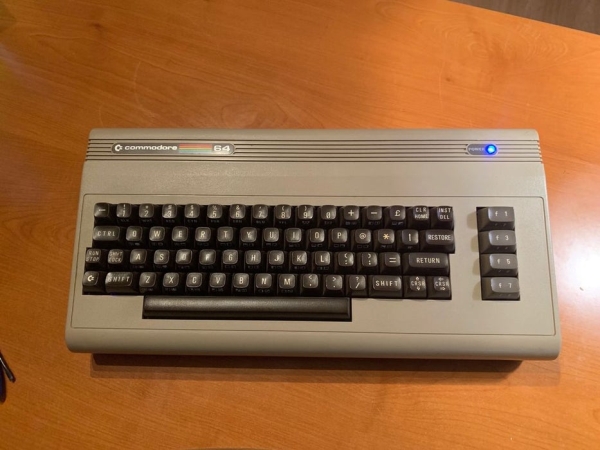
This instructable describes how to turn a Commodore 64 computer into a bluetooth keyboard. It involves programming a micro controller with the Arduino IDE and constructing a circuit board.
Supplies you’ll need (some are optional):
- Commodore 64 with keyboard (remove mother board, it is not used)
- (2) 74HC595 shift registers
- (8) 1N4148 diodes
- (3) 220 ohm resistors
- (1) RGB Led (common cathode)
- (1) Adafruit Feather M0 Bluefruit (other adafruit bluefruit nRF51 boards may work as well without modification to the instructions presented here)
- (1) 18×24 hole protoboard (larger sizes will work)
- (1) large breadboard
- (~50) male-male breadboard jumper cables
- (4) female-female jumper cables
- (1) 3.7V lipoly battery back with JST connector (I used 2000mAh)
- (1) slide switch (doesn’t necessarily have to be a slide switch, any switch could work)
- solder
- solder flux
- 30 guage wire
- (3-4) 2mm x 8mm screws
- (1) short male micro USB to female USB-A cable
- (1) USB-A male-male cable (3-6ft long, for charging)
- (1) 20 pin male pin header
- (1) 4 pin male pin header
- (1) JST PH 2.0 Plug Connector 100mm 2pin male connector wire (optional)
- (1) JST PH 2.0 Plug connector 100mm 2pin female connector wire (optional)
Tools you’ll need:
- soldering iron with fine tip
- helping hands or device to hold protoboard steady
- wire cutters
- philips screwdriver
- tweezers
- multimeter
- 30 guage wire strippers
- hot glue gun (optional)
- 3D printer (optional)
- computer with Arduino IDE installed
Step 1: Prepare Adafruit Feather M0 Bluefruit LE
First solder the header pins to the board if it didn’t come pre assembled.
Here is a good reference for the Adafruit Feather M0 Bluefruit LE:
Update the board to the latest firmware. My arduino sketch will not work unless the board is updated to at least 0.7.6. If you are running older firmware the sketch won’t work correctly or there will be performance issues. I confirmed my sketch runs flawlessly with versions 0.7.7 and 0.8.0. You can update the boards firmware over the air with your phone using the app Bluefruit LE Connect for (iOS or Android). I used the iOS app and you are given the option to upgrade or downgrade to many versions. Choose 0.7.7 or 0.8.0. I cannot guarantee that everything will work correctly for newer versions.
Next install the boards and libraries in the Arduino IDE needed for the sketch. Instructions can be found here:
Make sure you install both the Adafruit SAMD boards and the Arduino SAMD boards using the board manager.
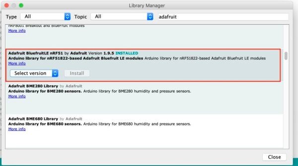
Also, install the Adafruit BluefruitLE nRF51 v1.9.5 using the library manager
Confirm that your board is working correctly by uploading some of the example sketches that you should see under example->Adafruit Bluefruit nRF51 if you installed the library correctly.
Finally, after confirming that the board is working properly, upload my sketch using the files provided in this step.
Step 2: Clean and Prepare Commodore 64 (as Needed)
Remove the Commodore 64 motherboard if you have one in there, it won’t be used.
Clean the Commodore 64 keyboard contacts. Before cleaning mine the space bar and the F1 keys didn’t always register when pressed. After the below process everything worked great.
- first desolder the wires connected to the shift lock
- remove the 23 tiny screws holding the bottom of the keyboard in place
- flip over the board
- then clean the contacts
- I used QD Contact Cleaner
- I sprayed some into a small cup and used q-tips to gently clean every contact until there was no more or very little black getting on to the q-tips
I tried the same cleaning process with rubbing alcohol at first and it wasn’t nearly as effective as the contact cleaner.
All the keys worked great after the cleaning.
Follow the reverse steps to reassemble the keyboard. Don’t forget to re-solder the wires to the shift lock key.
Step 3: Construct the Circuit on a Breadboard
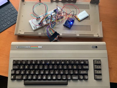
Now wire the circuit on the breadboard as shown in the Fritzing diagram. I used two breadboards in the picture, one large white breadboard and one small blue breadboard, just to spread it out a little. There is room to fit everything on one large white breadboard.
The picture of the ribbon coming from the Commodore 64 keyboard shows how to identify the pin numbers. Pin 1 is on the side where there is a missing hole (which would be pin 2).
It matters which direction the diodes in the circuit are placed. Make sure the dark bands on the diode are on the side indicated in the picture. The diodes I used are 1N4148.
All of the resistors are 220 ohm.
The RGB Led needs to be of the common cathode variety or it will not work correctly as wired in this circuit.
If everything has gone right, you should be able to connect the Commodore 64 to a device via bluetooth and have it work correctly as a bluetooth keyboard!
(note: comments in my arduino sketch also indicate what pins get connected to what)
(also note: pin 1 on the 74HC595 chip is where the dot is on the chip)
Step 4: Make a More Permanent Circuit.
Now that you’ve confirmed everything works properly its time to wire up a more permanent circuit. I did it using a technique taught in this instructable:
https://www.instructables.com/id/How-to-Prototype-…
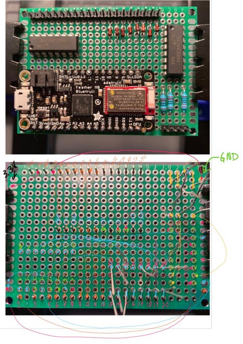
Shown in the photos is how I laid out my components.
I used a 20 pin male pin header and removed the second pin with pliers to make a place to attach the ribbon from the Commodore 64 keyboard. I also used a 4 pin male pin header to make a connector for the RGB LED.
I took a picture of that and then flipped it over and took a picture of it upside down.
I labeled all the pins on the diagram and drew in all the connections that needed to be made.
Be very careful and double check everything.
Once you’re sure everything is correct start soldering the connections using 30 gauge wire using the picture as a guide. I used a multimeter to make sure that there was an electrical connection between each thing I soldered and that there wasn’t between nearby pins that shouldn’t be connected.
I used female-female jumper cables and some crazy glue to make a cable for the RGB LED.
(note: on the horizontal 74HC595 I drew the connection for pins 9-16 underneath the numbers when the pins were really in the holes above the numbers)
Step 5: Add a Switch, USB Connector, and Mount to Finish It Off.
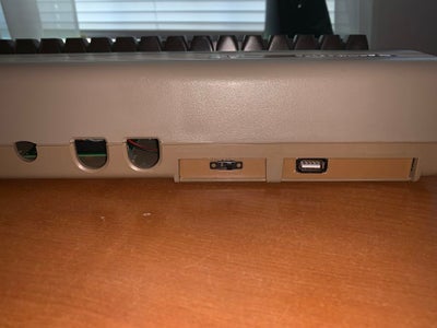
For the finishing stage:
- First I chose a location to affix the board and battery pack and hot glued them in place
- for the board I chose one of the screws that was for the motherboard and hot glued a screw there
- I hot glued two screws in other corners as well to hold it tightly in place and raise the circuit off the bottom a little
- I also hot glued the RGB LED in place of the old LED. You may not need to use hot glue, but my C64 case was damaged when I acquired it.
- then I extended the battery cable with a male and female 100mm JST connector and soldered a slider switch to be able to turn the bluetooth keyboard on and off
- next I acquired a short male micro-usb cable to female usb_a cable to use for charging
- I 3D printed a mount for the switch and USB cable (the stl file is attached)
- I needed to file the holes slightly to fit the switch and the USB cable
- I crazy glued the USB cable in place, the switch was good with friction alone
- Finally I hot glued the mounting plate in place
Step 6: Final Notes on Functionality
The LED is set to be:
- blue when the battery is good and it is connected to bluetooth
- green when the battery is good and it is not connected to bluetooth
- red when the battery needs to be charged
Note: in order to charge the battery the switch needs to be in the on position when connected to power via a USB cable.
Keyboard functionality:
I have only tested it on iOS devices and it can do everything I have thought to try. It should largely work on other systems, but I have not tested it.
The restore key is equivalent to the option key on a mac.
The Commodore key is equivalent to the command key on a mac.
The ctrl key is equivalent to the control key on a mac.
In order to use option shift commands press restore and the right shift key.
The right shift and left shift keys are different. In some cases they will not have the same results and are used to be able to type keys that are not shown on the Commodore keyboard.
right shift 7 is `
right shift = is |
right shift / is \
right shift : is {
right shift ; is }
tab is the left arrow in the top left corner of the keyboard
the clear/home button moves the cursor to the beginning of the line
right shift and clear/home moves the cursor to the end of the line
left shift clear/home highlights everything in the line behind the cursor
left shift and the cursor keys can be used to highlight text
Unmodified Function keys:
F1 = Play/Pause
F3 = Volume Up
F5 = Volume Down
F7 = Mute
Function keys when left shift key is pressed:
F1 = Media Next
F3 = Media Previous
F5 = Search
F7 = Home
Function keys when right shift is pressed:
F1 = Brightness +
F3 = Brightness –
F5 = Search
F7 = Toggle Virtual Keyboard
Source: Turn a Commodore 64 Into an IOS Bluetooth Keyboard