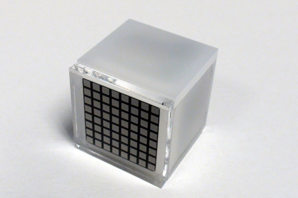
Laser Command is a game which I build using a 8×8 matrix LED and an Arduino Mini. This game was developed as a “sample” class project in S10-05833 Gadgets, Sensors and Activity Recognition in HCI. The class is taught by Scott Hudson at Carnegie Mellon University, and I’m doing TA for the class. The name “Laser Command” comes from an old game called Missile Command. In Missile Command, you are asked to shoot enemy’s missiles using missiles. In Laser Command, you shoot using laser, i.e., a laser pointer.
The most interesting part in this game is that the game uses a laser pointer as a two-dimensional input device in conjunction with a matrix LED. Here are a video, explanations of how it works, circuit diagrams and source code. I hope that these are enough for you to replicate and/or build on the technique 🙂
How it works
Essentially, I make a 8×8 matrix LED as a 8×8 light sensor array using two techniques.
In the followings, I will explain how the two techniques work using a simplified example shown below. The example consists of two digital ports (D0 and D1), two analog ports (A0 and A1) and four LEDs, i.e., a 2×2 matrix LED.
Reverse Bias
The first technique is well-known technique for using LEDs as light sensors. In this technique, we charge LEDs by applying reverse bias, and, then, measure how quickly the charged current leaks after stopping the reverse bias. In the example here, the technique works as follows:
- Reverse bias the LEDs by making D0 and D1 HIGH, and A0 and A1 LOW.
- Make D0 and D1 INPUT. Initially, both of them are HIGH because of current charged in the LEDs.
- Then, as the current leaks, D0 and D1 becomes LOW after a certain period.
The time required for the leakage to discharge the LEDs is inversely proportional to the brightness. So, if D0 becomes LOW quickly, we can know that one of (or both) the LEDs at the top row is pointed by a laser pointer. Likewise, if D1 becomes LOW quickly, the LEDs at the bottom row are pointed by a laser pointer.
This technique is sufficient if we just want to use a single LED as a light sensor. But, it is not sufficient if we want to use a matrix LED as a light sensor array. As described above, we can detect which row is pointed by a laser pointer, but we cannot distinguish which column is pointed because LEDs at the same row share a cathode.
So, we need one more technique to detect which column is pointed.
Direct Measurement
The second technique is not commonly used because it requires analog inputs. When we project strong light on LEDs, the LEDs are charged. In this technique, we directly measure the voltage generated by the charged LEDs as follows:
- Discharge all current stored in the LED by making all ports LOW.
- Then, measure voltage at A0 and A1 using analogRead(). The voltage is proportional to the brightness.
In my circuit, the voltage rises from 0.5V to 1.5V (this value depends on LEDs) when the LED is pointed by a laser pointer. This is not enough for digital input to become HIGH. But, the difference can be detected by analogRead(). Using this technique, we can detect which column is pointed by a laser pointer. Therefore, by using these two technique by turns, we can detect which LED is pointed.
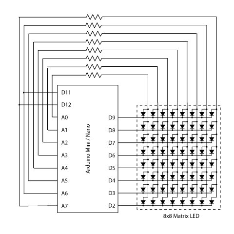
Circuit
Here is a circuit diagram which you can use with sensor sample source code. The circuit is a 8×8 matrix LED version of the example (2×2 version) discussed above. In the circuit, A6 and A7 are connected to D11 and D12 receptively. This is because these two ports do not work as digital outputs. This circuit requires eight analog inputs, so that you need an Arduino Mini, Nano or Mega (or whatever which supports more than eight analog ports). If you use an Arduino Duemilanove, you still can make a 8×5 matrix LED as a light sensor array with slight modifications.
In Laser Command, I also connected D10 to a piezo in addition to this circuit diagram.
For more detail: Using a laser pointer and a matrix LED as a two-dimensional input device