
Hi guys, welcome to today’s tutorial. Today we will look at how to use a hall effect sensor with Arduino.
A hall effect sensor is a sensor that varies its output based on the presence or absence of a magnetic field. This means that the output signal produced by a Hall effect sensor is a function of magnetic field density around it. When the magnetic flux density around it exceeds a certain pre-set threshold value, the sensor detects it and generates an output voltage sometimes called the hall voltage to indicate the presence of the magnetic field.
Hall sensors are becoming very popular due to their versatility and they are used in many different applications. One of the popular applications of hall effect sensors is in automotive systems where they are used to detect position, measure distance and speed. They are also used in modern devices like smartphones and computers and also used in different type of switches where the presence of a magnetic field is used to either activate or deactivate a circuit.
Hall sensors produce either analog or digital output depending on the particular sensor. Whichever type, they usually come in a three pin package with one pin to represent signal and the other two to provide power to the sensor. This makes easy the connection to any microcontroller.
For today’s tutorial, we will demonstrate how the hall effect sensor works by connecting it alongside a LED to an Arduino. The Arduino will be programmed such that when a magnet is brought close to the hall effect sensor, the LED comes on and when the magnet is removed, it goes off.
Required Components
The following components are required to build this project.
As usual, the exact components used for this tutorial can be bought via the links attached to each of the components listed above.
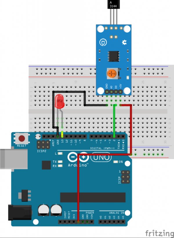
Schematics
The schematic for this project is a simple one, as all we have to do is connect the three pins of the hall sensor and an LED to the Arduino. Connect the components as shown in the schematics below.
Read more: Using a Hall Effect Sensor with Arduino