
Summary of A useful and simple IO Shield for Arduino
This article describes an Arduino experimentation shield designed to visually and functionally highlight I/O pin behavior. The shield features screw terminals for flexible connections, six digital outputs with LEDs and relays, and multiple analog/digital inputs capable of PWM or DAC output. It requires a 12V supply for Arduino YUN or power from an Arduino UNO.
Parts used in the Arduino Experimentation Shield:
- Screw terminals
- LEDs (six digital outputs)
- Relays
- Transistor driver circuits
- Analog input pins
- Digital input pins
- PWM/DAC capable pins (3, 5, and 6)
- 12-volt power supply
- Arduino YUN or Arduino UNO
In order to “visually” highlight the behavior of Arduino programs you must connect a device to the I/O pins, which gives you tangible signals. Normally, if you want to check if a program changes a level of an output pin, answering a command or executing a check routine, or event, you must check it by measuring the voltage level on the pin with a voltmeter. But if we connect this pin to a LED with the correct driver circuit, we can check the behavior of the program thanks to a switch in the LED state: it could be on, off, or partially on, if you connect it to an analog output pin. In a similar way, if the output pin is connected to a relay, we can drive external loads with ease. The same applies to the digital or analog input pins, and analog outputs.
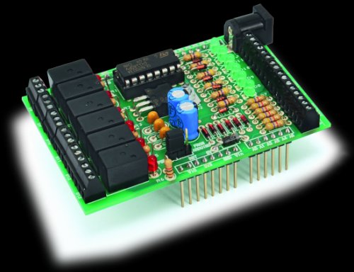
To give a more professional appearance to our projects and to further ensure the reliability of the connections we prepared a experimentation shield in “Arduino” style, indicated mostly for Arduino YUN (but that can also be used with earlier versions).
To give maximum flexibility to the use of the shield, all external connections are mounted on screw terminals. The shield provides six digital outputs connected to as many LEDs to display the status plus relays to activate external loads. You can connect LED strips, cooling fans, buzzers or whatever you prefer. There are also six analog and six digital multifunction inputs three of which can be used as PWM or DAC analog outputs if you prefer (pin 3, 5 and 6.)
The board requires a separate power supply of 12 volts if it is used with Arduino YUN, or it can get power directly from Arduino UNO.
As you can see in the circuit diagram the shield is divided into sections. Each section is specialized in bringing outside the possibility to connect to a specific type of I / O pin. Within each section of the circuit diagram is repeated identically for each of the pins.
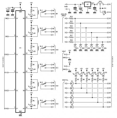 Let’s start from the section that serves the digital output pins, which correspond to Arduino pin 8, 9, 10, 11, 12 and 13.
In this section each pin drives a transistor driver circuit coupled to a relay. On the screw terminals all the terminals of the relay are available, the central terminal C, the “normally closed” NC terminal and the “normally open” NO one. The arrangement of the ends on the terminals is visible in the ” Mounting Plan”.
For more detail: A useful and simple IO Shield for Arduino
- How can you visually check the behavior of an Arduino program?
You connect a device like an LED with a driver circuit to the I/O pins to see tangible signals such as on, off, or partially on states. - What is the primary purpose of the experimentation shield described?
The shield provides a professional appearance and ensures reliable connections while allowing users to drive external loads easily. - Which Arduino boards are compatible with this shield?
The shield is indicated mostly for Arduino YUN but can also be used with earlier versions like Arduino UNO. - How many digital outputs does the shield provide?
The board provides six digital outputs connected to LEDs and relays corresponding to Arduino pins 8 through 13. - Can the input pins be used as outputs?
Yes, three of the six digital multifunction inputs can be used as PWM or DAC analog outputs if preferred. - What power supply is required for Arduino YUN usage?
The board requires a separate power supply of 12 volts when used with Arduino YUN. - How does the shield allow for connecting external loads?
All external connections are mounted on screw terminals that provide access to relay terminals including central, normally closed, and normally open contacts. - What types of devices can be connected to the screw terminals?
You can connect LED strips, cooling fans, buzzers, or whatever you prefer to activate external loads.
