Summary of Use an LM317 as 0 to 3V adjustable regulator
This article details a circuit design using an LM317 adjustable regulator to achieve output voltages below its standard 1.25V minimum, specifically targeting a 0 to 3V range. It critiques common methods like diode biasing due to temperature instability and expensive IC alternatives. The proposed solution utilizes a temperature-stabilized constant-current source to create a necessary negative bias voltage, enabling precise low-voltage regulation with simple components and zero adjustment capabilities.
Parts used in the LM317 Adjustable Regulator Project:
- Fairchild Semiconductor LM317
- D1 (Diode)
- Q1 (Transistor)
- R5 (Resistor)
- R6 (Resistor)
- R3 (Resistor)
- R2 (Resistor)
- R1 (Resistor)
Most engineers know that they can use an inexpensive, three-terminal adjustable regulator, such as Fairchild Semiconductor’s LM317, as an adjustable regulator to only some necessary value of voltage, such as 36 or 3V. This value cannot be less than 1.25V without employing other approaches, however. The devices’ inner reference voltage is 1.25V, and their output voltage accordingly cannot be less than this value without potential bias (Reference 1). One way to solve this problem is to use a reference-voltage source based on two diodes (Reference 2). Although this approach is suitable for a 1.2 to 15V or higher-voltage regulator, it is not appropriate for an extra-low-voltage fixed- or adjustable-voltage regulator. The two 1N4001 diodes it employs do not provide the needed potential bias of 1.2V, and they have additional temperature instability of approximately 2.5 mV/K (Reference 3). Hence, additional temperature drifting of the output voltage is approximately 100 mV; it is more than 6% for a 1.5V output voltage and 10% for a 1V output voltage if you adjust the temperature to 20°C—a typical indoor situation. You can solve these problems by using a Fairchild Semiconductor LM185 or an Analog Devices AD589 adjustable-voltage-reference IC. These devices are expensive, however, and, in this case, they require not only additional zero adjustment but also matching. These adjustments at their reference voltages are 1.215 to 1.255V and 1.2 to 1.25V for the LM185 and AD589, respectively. Note that the reference voltage of the LM317 is 1.2 to 1.3V.
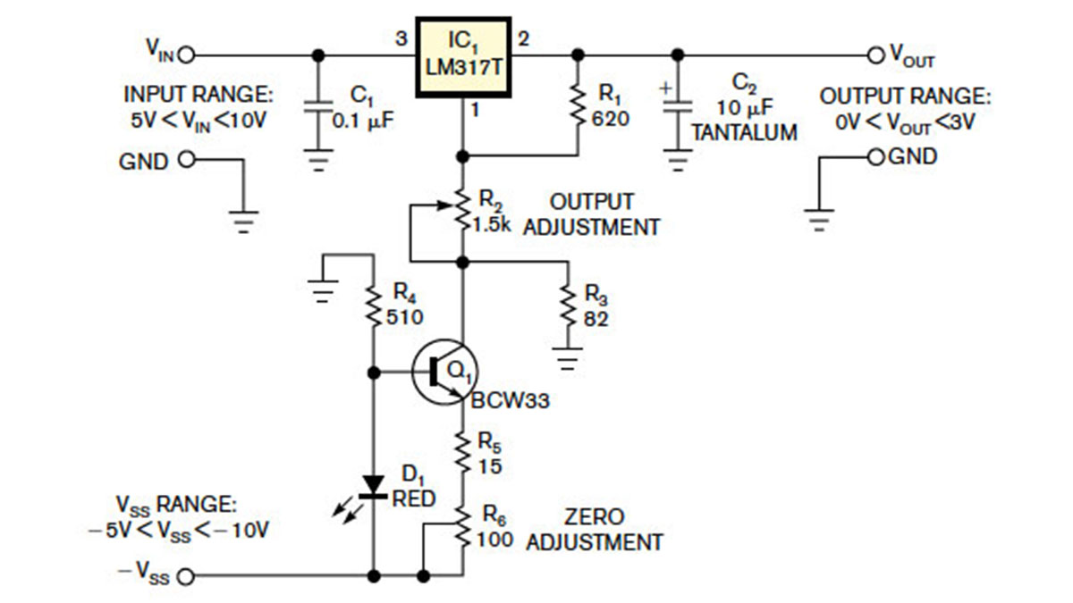
Figure 1 shows an inexpensive approach using a simple 0 to 3V adjustable regulator. You implement the necessary potential bias using a simple temperature-stabilized constant-current source (Reference 4). You calculate this current source using the following equation: I=(VF–VEBO)/(R5+R6), where VF is D1’s forward voltage of approximately 2V and VEBO is Q1’s emitter-base voltage of approximately 0.68V. The current is approximately 1.32/(R5+R6). The constant-current source creates a bias voltage of approximately –1.25V on resistor R3. You implement the zero adjustment using resistor R6, which can change the current of the constant-current source. Resistor R5 protects transistor Q1. You can use D1 as a light indicator. You can adjust the output voltage using resistor R2. Calculate the output voltage as follows: VOUT=VREF(1+R2/R1)–VR3, where VREF is the reference voltage of IC1 and VR3 is some compensative voltage of resistor R3. You should establish this voltage to equal the reference voltage for its compensation. In this case, VOUT=VREF(R2/R1). With R2 having a value of 1.2 kΩ,this circuit found use as the equivalent of a typical battery with an output voltage of 1.56V for development projects.
For More Details: Use an LM317 as 0 to 3V adjustable regulator
- Why can't an LM317 regulate below 1.25V normally?
The device's inner reference voltage is 1.25V, preventing lower outputs without potential bias. - What are the drawbacks of using two 1N4001 diodes for biasing?
They lack sufficient potential bias and cause significant temperature instability, leading to over 6% drift at 1.5V. - Why are LM185 or AD589 ICs not always the best choice here?
These devices are expensive and require additional zero adjustment and matching procedures. - How does the proposed circuit solve the low-voltage limitation?
It uses a simple temperature-stabilized constant-current source to create a necessary potential bias. - What is the function of resistor R6 in this design?
Resistor R6 implements the zero adjustment by changing the current of the constant-current source. - What role does resistor R5 play in the circuit?
Resistor R5 protects transistor Q1 within the constant-current source. - Can D1 serve as a light indicator in this setup?
Yes, you can use D1 as a light indicator. - How is the final output voltage calculated when VR3 equals VREF?
The formula simplifies to VOUT=VREF(R2/R1) when the compensative voltage equals the reference voltage.