
Summary of Serial seven segment LED display shield
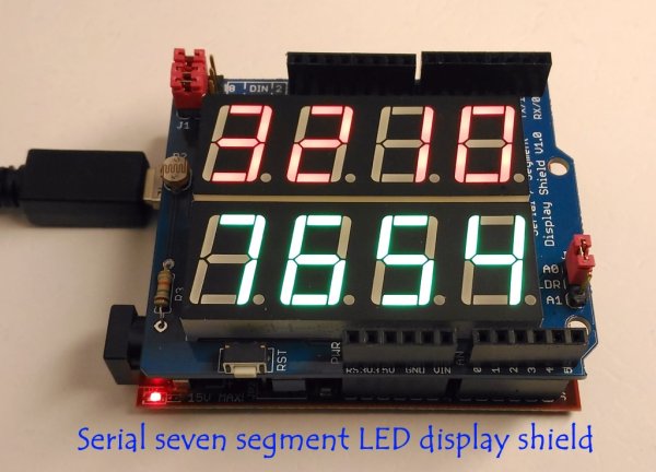
This article details a serial seven-segment LED display shield for Arduino Uno, featuring eight 0.56-inch displays driven by a MAX7219 chip. The shield includes an LDR circuit for adaptive brightness control based on ambient light levels, with demo code and Eagle CAD files provided.
Parts used in the Seven Segment LED Display Shield:
- Arduino Uno or compatible boards
- MAX7219 display driver chip
- Eight 0.56″ seven segment LED displays (common-cathode type)
- Light dependent resistor (LDR)
- 10K fixed value resistor
- Header pins with shunt jumpers
- Eagle CAD files
- Demo code
Seven segment LED displays are brighter, more attractive, and provide a far viewing distance as well as a wider viewing angle compared to LCD displays. This project describes a serial seven segment LED display shield for Arduino Uno or compatible boards. The shield consists of eight 0.56″ seven segment displays that are driven by one MAX7219 chip. The shield also features a light dependent resistor (LDR) to implement adaptive brightness control to the LED displays. The LDR output can be fed to A0 or A1 analog input channel of Arduino to read the surrounding illumination level. Arduino can then use that information to adjust the brightness of the LED displays. A demo code and Eagle CAD files are also provided in the latter part of the article.
MAXIM’s MAX7219 display driver chip provides a 3-wire serial (SPI) interface to drive up to eight seven-segment LED displays (common-cathode type). Included on the chip are a BCD decoder, multiplex scan circuitry, segment and digit drivers, and an 8×8 static RAM to store the digit values. The maximum segment current for all LEDs is set through an external resistor. However, the device is also capable of providing a 16-level brightness control of the LED segments via software. For more details on the internal block diagram and operation of MAX7219, read my earlier project Serial 4-digit LED display as well as Maxim’s datasheet.
Display Shield Features
- Consists of eight seven segment LED displays (0.56″height) arranged in two rows of four digits.
- Header pins (1) with shunt jumpers for connecting the DIN, CLK, and LOAD pins of MAX7219 to Arduino pins. With jumpers, you can connect DIN to pin 8 or 2, CLK to pin 9 or 3, and LOAD to pin 10 or 4.
- An LDR circuit for detecting ambient light level. The LDR output can be connected to A0 or A1 pins via jumper J2.
These features are highlighted in the pictures below.
Adaptive brightness control
An automatic brightness adjustment is basically a closed loop system that has the capability to assess ambient light and adjust the brightness of the display accordingly. In this shield, a general purpose LDR and a fixed value resistor (10K) are connected in series between the power supply and ground pins to create a voltage dividing network. The resistance of a typical LDR is less than 1 KΩ under bright lighting condition. Its resistance could go up to several hundred KΩ under extremely dark condition. Therefore, the voltage across the 10K resistor increases proportionally with the surrounding illumination. For the given setup, the voltage across the 10K resistor can vary from 0.1V (under dark condition) to over 4.0V (under very bright illumination). Arduino can be programmed to read this analog voltage through its analog input channel (A0 or A1) and then sends out appropriate signals to the MAX7219 driver to adjust the brightness of the seven segment LED displays. I have explained this topic in more detail in one of my previous articles.
Read More: Serial seven segment LED display shield
- How does the adaptive brightness control work?
An LDR and a 10K resistor form a voltage divider where the voltage across the resistor increases with illumination, allowing the Arduino to adjust display brightness. - What interface does the MAX7219 chip use?
The MAX7219 provides a 3-wire serial SPI interface to drive up to eight seven-segment LED displays. - Can the brightness be controlled via software?
Yes, the device offers 16-level brightness control of the LED segments through software commands. - Which analog input channels can read the LDR output?
The LDR output can be connected to either the A0 or A1 analog input channel of the Arduino. - What is the resistance range of the typical LDR described?
The resistance is less than 1 KΩ under bright lighting and can rise to several hundred KΩ in extremely dark conditions. - How are the DIN, CLK, and LOAD pins connected?
Header pins with shunt jumpers allow connecting these pins to Arduino pins 8/2, 9/3, and 10/4 respectively. - What components are included inside the MAX7219 chip?
The chip includes a BCD decoder, multiplex scan circuitry, segment and digit drivers, and an 8×8 static RAM. - What files are provided with this project?
A demo code and Eagle CAD files are provided in the article.
