
Summary of USB to RS485 converter
This article details the design of a custom USB-to-RS485 converter using an STM32F0 microcontroller, addressing the scarcity of RS232 interfaces. The project features a minimal one-sided PCB with three active components and includes firmware to handle bidirectional data flow and serial line coding interpretation via USB CDC.
Parts used in the Custom USB-to-RS485 Converter:
- STM32F0 Microcontroller
- Voltage Regulator
- RS485 Transceiver
- USB Interface
- UART Interface
- One-sided PCB
Testing of sensors with RS485 using PC without proper interface is not possible. Since RS232 interfaces are very rare, the interface should be hooked to USB. The interface between USB and RS485 can be soldered with one of the many FTDI interfaces with added RS485 driver, or bought as assembled module. There is always the third option. I made it from scratch.
I took smallest STM32F0 with USB and UART interface. The best thing with UART in the STM32F0 is that signal for driver enable is provided within hardware. The complete pinout of the microcontroller is:
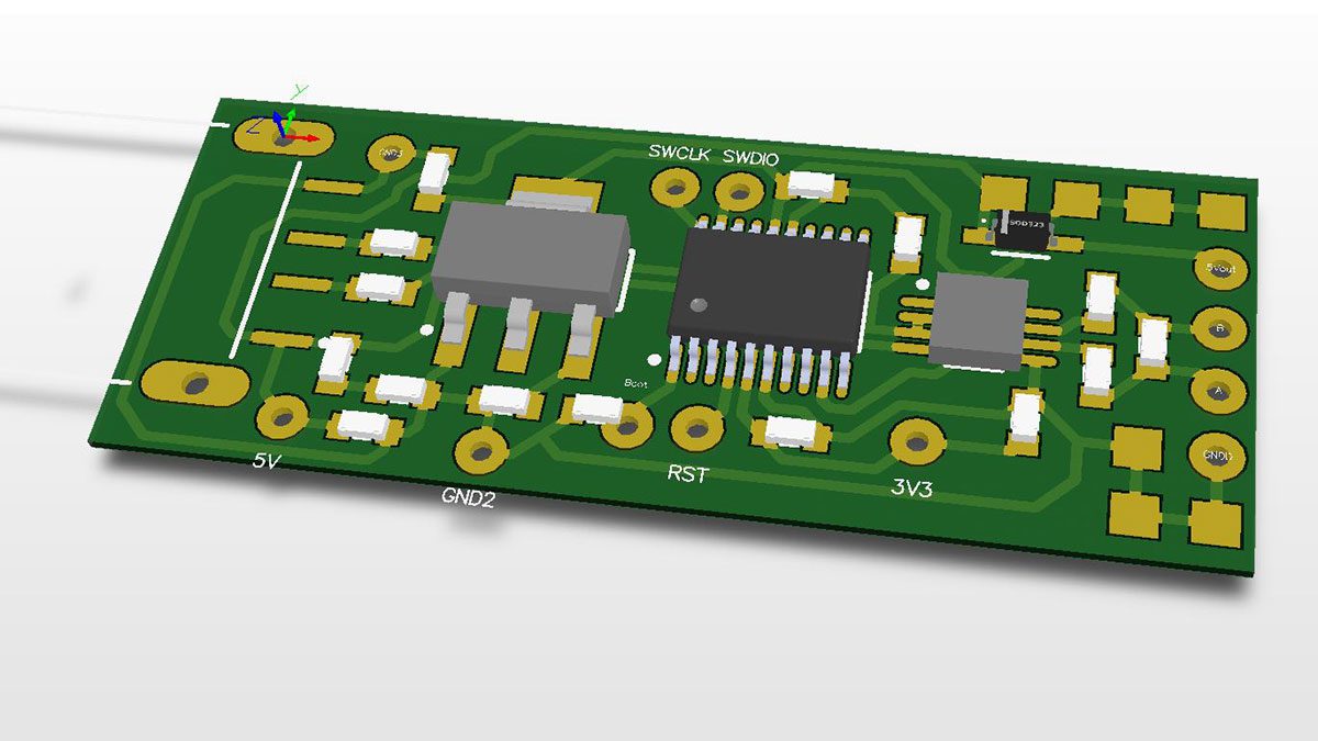
The hardware part is easy. The complete PCB is one-sided. I kept it as minimalistic as possible. There are three active components: voltage regulator, microcontroller and RS485 transceiver. The complete schematic:
Here is complete altium project: USB-RS485
The documentation in PDF file: USB2RS485-doc
For all who want to produce the PCB with the toner transfer technology is here the PCB, mirrored and with 1:1 scale: USB2RS232-tonertransfer
And the most useful sheet of documentation for assembling:
After soldering it’s time to put the module to life:
The project, generated from the MX cube is almost all we need. There are few things to add:
- retransmit bytes received from USB to UART
- forward bytes received via UART to USB
- add serial line coding interpretation and reflect it in the hardware UART
The code for sending bytes from UART to USB is within main endless loop:
if (HAL_UART_Receive_IT(&huart2, &aRxBuffer, 1) == HAL_OK) CDC_Transmit_FS(&aRxBuffer,1) |
Code to send data from USB to UART is within CDC_Receive_FS() function:
static int8_t CDC_Receive_FS (uint8_t* Buf, uint32_t *Len)
{
 /* USER CODE BEGIN 6 */
 USBD_CDC_SetRxBuffer(hUsbDevice_0, &Buf[0]);
 USBD_CDC_ReceivePacket(hUsbDevice_0);
 HAL_UART_Transmit(&huart2, Buf, *Len, 100);
 return (USBD_OK);
 /* USER CODE END 6 */
}
|
And finally, the code to set the UART line parameters are within USB CDC_Control_FS() function:
  /*******************************************************************************/
 /* Line Coding Structure */
 /*-----------------------------------------------------------------------------*/
 /* Offset | Field | Size | Value | Description */
 /* 0 | dwDTERate | 4 | Number |Data terminal rate, in bits per second*/
 /* 4 | bCharFormat | 1 | Number | Stop bits */
 /* 0 - 1 Stop bit */
 /* 1 - 1.5 Stop bits */
 /* 2 - 2 Stop bits */
 /* 5 | bParityType | 1 | Number | Parity */
 /* 0 - None */
 /* 1 - Odd */
 /* 2 - Even */
 /* 3 - Mark */
 /* 4 - Space */
 /* 6 | bDataBits | 1 | Number Data bits (5, 6, 7, 8 or 16). */
 /*******************************************************************************/
 case CDC_SET_LINE_CODING:
 linecoding.bitrate = (uint32_t)(pbuf[0] | (pbuf[1] << 8) | (pbuf[2] << 16) | (pbuf[3] << 24));
 linecoding.format = pbuf[4];
 linecoding.paritytype = pbuf[5];
 linecoding.datatype = pbuf[6];
 huart2.Init.BaudRate = linecoding.bitrate;
 switch (linecoding.format)
 {
 case 0 : huart2.Init.StopBits = UART_STOPBITS_1; break;
 case 1 : huart2.Init.StopBits = UART_STOPBITS_1_5; break;
 case 2 : huart2.Init.StopBits = UART_STOPBITS_2; break;
 }
 switch (linecoding.paritytype)
 {
 case 0 : huart2.Init.Parity = UART_PARITY_NONE; break;
 case 1 : huart2.Init.Parity = UART_PARITY_ODD; break;
 case 2 : huart2.Init.Parity = UART_PARITY_EVEN; break;
 }
 //UART_WORDLENGTH_7B
 switch (linecoding.datatype)
 {
 case 7 : huart2.Init.WordLength = UART_WORDLENGTH_7B; break;
 case 8 : huart2.Init.WordLength = UART_WORDLENGTH_8B; break;
 }
 HAL_RS485Ex_Init(&huart2, UART_DE_POLARITY_HIGH, 0, 0);

 break;
|
The complete project is hosted on GitHub>>> https://github.com/s54mtb/USB2RS485
Read more: USB to RS485 converter
-
Why is a USB interface necessary for testing RS485 sensors?
RS232 interfaces are very rare, so the interface must be hooked to USB. -
What makes the UART in the STM32F0 beneficial for this project?
The signal for driver enable is provided within the hardware. -
How many active components are included in the complete PCB?
There are three active components: voltage regulator, microcontroller, and RS485 transceiver. -
What technology can be used to produce the PCB at home?
The toner transfer technology can be used to produce the PCB. -
What functions does the code added to the MX cube project perform?
The code retransmits bytes from USB to UART, forwards bytes from UART to USB, and adds serial line coding interpretation. -
How are stop bits configured in the Line Coding Structure?
Stop bits are configured based on the bCharFormat value where 0 is 1 Stop bit, 1 is 1.5 Stop bits, and 2 is 2 Stop bits. -
Where is the complete project hosted?
The complete project is hosted on GitHub.
