Summary of Uno The Arduino Robot
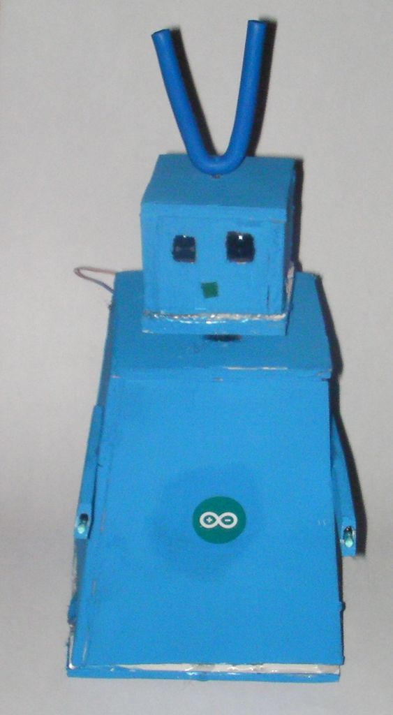
Uno is a beginner-friendly Arduino robot featuring a blinking nose, moving antennas, rotating head, IR sensor, and twin motor gearbox. Constructed from accessible materials like foam board and Fimo, it serves as an excellent introduction to robotics and microcontroller programming.
Parts used in the Uno Robot:
- Foam board
- Fimo
- 4 Rare Earth magnets
- 4 small metal plates (from transformer)
- Thrust bearing
- LEDs
- IR distance sensor
- Twin motor gear box with wheels
- JST connector
- 2 9VDC pin solenoid
- Arduino
- A-B USB cable
- Power source
- Switch
- Servo
- 3 TIP 120 or 121 transistors
- Male header pins
- School glue
- Weld bond
- Hot Glue gun
- Xato knife/carpet cutter
- Pen
- Wire strippers/cutters
- Pliers
- Clear tape
- Copper clad
- Ferric chloride
- 2 lever switch
- 2 1 µF capacitor
- 30 gauge wire
- 5 1k ohm resistors
- 1 470 ohm resistor
- 2.1mm barrel Jack
Meet Uno the Arduino powered robot. Some functions include a blinking nose, moving antennas, rotating head, IR distance sensor, twin motor gear box and rotation counters. Uno is made with relatively easy to obtain parts. This project provides a good introduction to Arduino.
 robot.skp475 KB
Step 1: Materials
Material and tools
• Foam board
• Fimo
• 4 Rare Earth magnets
• 4 small metal plates (from transformer)
• Thrust bearing
• LEDs
• IR distance sensor
• Twin motor gear box with wheels
•JST
• 2 9VDC pin solenoid
• Arduino
• A-B USB cable
•power source
•switch
• Servo
•3 TIP 120 or121
•male header pins
• School glue
• Weld bond
• Hot Glue gun
• Xato knife/carpet cutter
• Pen
• Wire strippers/cutters
•Pliers
•Clear tape
• copper clad
• ferric chloride
• 2 lever switch
• 2 1 µF capacitor
• 30 gauge wire
• 5 1k ohm resistors
• 1 470 ohm resistor
• 2.1mm barrel Jack
Step 2: Cutting
 Robot template.pdf81 KB
Step 3: The Base
Cut out the circle in template B then assemble the gear box to 1: 60. Draw a line through the center of the template. Match the center of the gear box with this line. mark the template on each side of the mounting plate, do the same for the wheels, then cut(see photo). Hot glue the gear box in place then glue the thrust bearing in place(see photo).
Step 4: The Body
Find the center of template F then drill a 3/16” hole. Put servo knob in the hole and trace the servo then cut out this piece. Reinsert the servo and hot glue it in place. To form body glue 3 A’s and 1 F together with white school glue (see photo)then paint. Find the center of piece D and drill a 5/32” hole. Then line up the hole in the servo horn with the hole in the foam board and hot glue. Drill a 1/4” hole through piece D and F(see picture for position).
• Fimo
• 4 Rare Earth magnets
• 4 small metal plates (from transformer)
• Thrust bearing
• LEDs
• IR distance sensor
• Twin motor gear box with wheels
•JST
• 2 9VDC pin solenoid
• Arduino
• A-B USB cable
•power source
•switch
• Servo
•3 TIP 120 or121
•male header pins
• School glue
• Weld bond
• Hot Glue gun
• Xato knife/carpet cutter
• Pen
• Wire strippers/cutters
•Pliers
•Clear tape
• copper clad
• ferric chloride
• 2 lever switch
• 2 1 µF capacitor
• 30 gauge wire
• 5 1k ohm resistors
• 1 470 ohm resistor
• 2.1mm barrel Jack
For more detail: Uno The Arduino Robot
-
What functions does the Uno robot have?
Functions include a blinking nose, moving antennas, rotating head, IR distance sensor, twin motor gear box, and rotation counters. -
Is this project suitable for beginners?
Yes, the project provides a good introduction to Arduino and uses relatively easy to obtain parts. -
How do you attach the servo to the body?
You drill a 3/16 inch hole in template F, insert the servo knob, trace and cut the piece, then hot glue the servo in place. -
What tools are required for cutting templates?
You need a new Xato knife blade and a straight edge to cut out the printed templates from foam board. -
How is the gear box mounted on the base?
The center of the gear box is matched with a line drawn through the center of template B, then hot glued in place with a thrust bearing. -
What power options are listed for the robot?
The materials list includes a power source, a 2.1mm barrel Jack, and a switch for operation. -
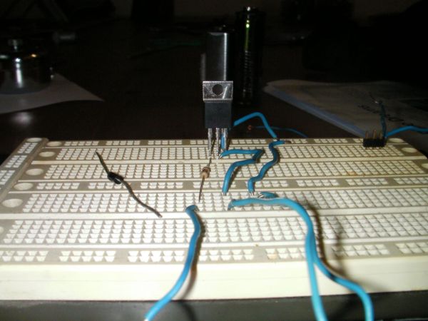
Which electronic components are needed for circuit assembly?
Necessary components include copper clad, ferric chloride, capacitors, resistors, transistors, and male header pins.