Summary of Universal clock suitable for visually impaired using Arduino
This article details a low-cost assistive device for the visually impaired, built for under $5. It functions as a clock, stopwatch, egg timer, tape measure, and water level detector by using an Attiny85 microcontroller to output beep sequences representing numbers via pitch and duration variations. The project emphasizes affordability and accessibility, utilizing common components like an Altoids tin, a rotary encoder, and a piezo speaker within a compact housing.
Parts used in the Assistive Device:
- Arduino duemillanove or alternative
- Shield for programming attiny processors
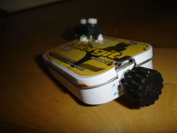
- Altoids tin or alternative container
- Battery holder (for 2x1AA batteries)
- Attiny85 microcontroller and socket
- P RE-24 mechanical rotary encoder
- Momentary switches x 2
- Resistors x 6 (10kohm)
- Piezo speaker
- Paperclips, long wire, 9V batteries/connectors, and plastic bottle cap
I was googling around looking for some sort of device I could make using arduino and stumbled upon eshop with devices for visually impaired. What really shocked me was the price. I mean-I do realize that such sorts of devices are not really mainstream, but still, it was kinda high. So I decided to make something similar while keeping the price as low as possible. I ended up making a clock, stopwatch, egg timer, tape measure and water level detector for under 5 bucks.
Step 1: Basic principles
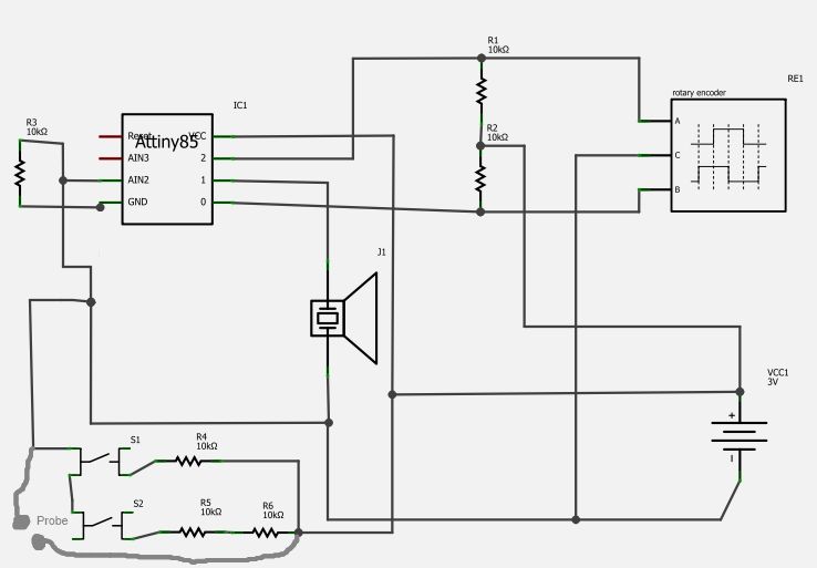
First off, I’m sorry to disappoint, but in current design, my device doesn’t talk. Instead, it beeps out a specific sequence, telling you the number. It actually is quite like roman numerals. “17” is “XVII”. Each numeral up to fifty (that’s 1, 5, 10, 50) has corresponding beep sequence in my program. Those sequences vary by pitch and also by number of beeps. So 17 would be X-X-X—-V-V—-I—-I where “X” “V” and “I” are tones of different pitch and dashes (“-“) illustrate length of the delay. The way routines communicate is shown in the picture below. Basically, I would like you to notice several things:
-1) Value of null has a specific beep sequence for it.
-2) Buttons and probe (for before mentioned water level detector) are connected via 1 analog pin.
-3) Encoder interrupts the processor, but overflows of encoder related values are handled without jumping out of program.
-4) Encoder needs debouncing. I wasn’t able to do it correctly so I borrowed working routine fromHERE. (“Another Interrupt Library THAT REALLY WORKS (the Encoder interrupts the processor and debounces like there is no tomorrow”). by raffbuff)
Step 2: Schematics ‘n’ stuff
You will need:
———————
Arduino duemillanove (to program it) or alternative
Some sort of shield for programming attiny processors with arduino (look it up on instructables; if you’re lazy to build one, just hook your attiny up like SO.)
Altoids tin or alternative. (Quite frankly, I used alternative).
Battery holder (I used 2x1AA)
attiny85 (presumably -20PU) and socket (important)
rotary encoder (mechanical, I used P RE-24 rotary encoder, as the estimated lifespan is about 100 000 cycles and it’s less than 2 bucks.)
Momentary switch x 2– I used some from an old keyboard, however, I DO NOT recommend you to do so. Although they have really good mechanical debouncing, they are fairly huge and it’s not that comfortable to press them with your thumb.
resistor x 6. They need to be same value and it’d probably be good for them to be somewhere in kiloohms range. However, exact value isn’t crucial. I used 10kohm.
Piezo speaker. I had some really flat one lying around, but maybe those in plastic housing (cylindrical ones) would be louder. I don’t know.
Some paperclips, long wire, 2 old 9V batteries/9V connectors and plastic bottle cap for probe
Tools you will need: Solder, soldering iron, drill (optional), combination pliers, duckt tape, perfboard, scissors, and some sort of glue, I used hot glue and poster clay. Also. Lot of wire.
Step 3: Assembly
First of all, you need to somehow insulate conductive parts of can from electronics. To do so, I used duckt tape (not visible on photos). So, this is the first thing you gotta do. Then cut a piece of universal perfboard and basically resemble schematics given in step 2. while doing so, make sure you don’t solder rotary encoder, buttons and piezo directly to the board. Instead, solder a wire (flexible one, so that it bends nice and smooth) between aforementioned components and socket pins. And don’t connect the buttons just yet. Leave wires from “+” and pin 3 (for buttons and probe, that is 4 wires, 2 from both socket pin and “+”) unconnected. You’ll solder them later. For pullup resistor for buttons, it might generally be a good idea to put a heat shrink tubing over it to prevent short circuit. Same goes for pretty much all resistors, if you decide to not put them on perfboard.
What you should have by now:
Perfboard with attiny socket on it with piezo hanging on 2 wires, rotary encoder hanging on three, with two wires to battery holder and 4 wires not going anywhere (2 from “+” and 2 to pin 3 on socket). Now it’s about time to put the components in place.
Putting the encoder in place
Measure where would you like to put it, mark a hole there and then just drill several holes with your drill in that hole. (What kind of sentence is that? O_o). Basically, just keep drilling until the holes fill the circle you’ve marked. Then use your mums best scissors to make the individual holes one big hole. Then twisting them, make the big (=final) hole rounder and you’re good to go. The encoder should have a tip to make it stable when twisting. (See attached images.) So if it does, just drill an extra hole for this tip. Then unscrew the nut of encoder, place it in position and screw it back using pliers.
Drilling
Simply drill some holes you’ll poke the wires through for buttons and probe. The holes for buttons will naturally be on the lid of the can, in the left corner. Just make sure you don’t drill the hole right underneath the edge of the buttons where the solder joint will be, otherwise you might run into short circuit. See attached images. Then just solder the buttons and probe. If you didn’t put the resistors on the perfboard and want to connect them directly to the buttons instead, now it might be a good time to do so. Secure the buttons in place with some poster clay/hot glue/whatever. Same goes for the perfboard itself, I used a wire that goes round the tin, but that wasn’t the most brilliant idea I’ve had.
Step 4: Probe
To build the probe, just tear open an old 9v battery and glue and solder together some wire, plastic bottle cap and paperclips…
Some sort of shield for programming attiny processors with arduino (look it up on instructables; if you’re lazy to build one, just hook your attiny up like SO.)
Altoids tin or alternative. (Quite frankly, I used alternative).
Battery holder
attiny85
rotary encoder
Momentary switch x 2
resistor x 6
Piezo speaker
Some paperclips, long wire, 2 old 9V batteries/9V connectors and plastic bottle cap
For more detail: Universal clock suitable for visually impaired using Arduino
- How does the device communicate numbers?
The device uses specific beep sequences with varying pitches and delays to represent numerals up to fifty. - Can the device speak text?
No, the current design does not talk but instead beeps out sequences. - What is the best way to handle encoder interrupts?
You should use a debouncing routine, such as one from the Another Interrupt Library, to handle encoder values without jumping out of the program. - How are the buttons and probe connected?
Buttons and the probe are connected via a single analog pin. - What tool is recommended for drilling holes for the encoder?
A drill is used to make several small holes that can then be combined into one larger hole for the encoder. - Does the exact resistor value matter?
The exact value is not crucial, but they should be the same value and preferably in the kiloohms range. - How do you insulate the conductive parts of the tin?
Duct tape should be used to insulate the conductive parts of the can from the electronics. - What materials are needed to build the water level probe?
You need paperclips, long wire, old 9V batteries or connectors, and a plastic bottle cap.