Summary of Build A Full Binary Clock Using Arduino
This article provides a tutorial for building a compact binary clock featuring seconds, minutes, and hours. The author addresses the lack of existing guides by detailing a project that uses multiplexing to control 20 LEDs efficiently with an ATtiny84 microcontroller and an SN74HC164 shift register. The build involves creating two custom PCBs, designing a stand from polymorph or origami, and programming the controller using an Arduino as an ISP.
Parts used in the Binary Clock:
- 20 LEDs (5mm recommended)
- 6 PN2222 transistors
- 2 push buttons
- 2 1K resistors
- 10 resistors for LEDs (470ohm used)
- Various wire for connections
- ATtiny84 microcontroller
- SN74HC164 shift register
- DIP socket
- 5V power supply or USB charger
- Two PCB boards (4cm x 6cm and 3cm x 7cm)
- Polymorph or origami material for stand
I was wandering the internet looking for a good Arduino tutorial on how to build a binary clock with seconds, but I could not find one. So now I am writing this for you to have a binary clock with seconds, minutes, and hours.
What I did:
-Because controlling 20 LEDs individually for this cube would be messy, I multiplexed.
-I used an ATtiny84 and a SN74HC164N to control the clock. This makes the clock cheaper and smaller.
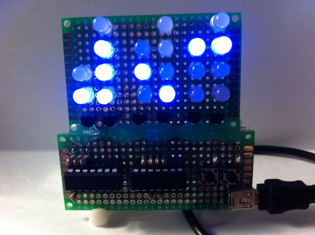
-I built it all on two PCB boards and affixed a stand, power plug, and buttons.
Step 1: Parts List
Somethings you have to have to make a binary clock, others are optional and I will try to give you ideas to use what you have.
Required Parts:
-20 LEDs, any color I used 5mm I wouldn’t recommend 10 unless you have the space
-6 PN2222 transistor, or any that you have that are similar
-2 push buttons, any flavor of interface you want to try would work buttons are easy
-2 1K resistors, for the buttons
-10 resistors for LEDs, I used 470ohm you could use as low 100ohm but they would be very bright at night
-various wire for connections
Choices:
Controller
-I used ATtiny84 and SN74HC164, I choose it because it was small, cheep, and easy to use with this option you will use the shift register to control one side of the LED matrix
-ATmega, any of this series would work as long as you have a programmer and the space
-Arduino Board, I don’t recommend spending the money on this option and it also takes up a lot of space
-ATtiny with only 6 I/O if you use two shift registers
-The library is written for Arduino and feels free to use anything else that you would re-code
*Use a DIP socket for whichever controller you choose to use.
Power
-I used USB charger and cable to power it
-any 5V power supply would work, just make sure it works with your controller
PCB
-Some type of board is needed. I used two small boards, 4cm x 6cm and 3cm x 7cm. I have seen cardboard used for the LEDs but I do not recommend cardboard for the controller.
Stand
-I used polymorph, it’s cool stuff to have around
-origami would work
Step 2: My Multiplexing
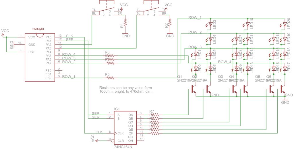
I use the SN74HC164 shift register and PN2222 transistor to shift on each column of the LED matrix to ground faster than the eye can see. When the correct column is grounded then the ATtiny then outputs HIGH to the LED that represents the time.
When a the transistor emitter is connected to ground the transistor will provide ground, from collector, if the base is connected to Vcc.
Step 3: Wiring
Wiring will depend on your design choices but here are the connections you need to make.
1. Solder your LED matrix as in the diagram, note it is drawn from the back make sure the cathode and anodes are corrected to ground and Vcc, respectively
2. Connect the LEDs ground to the emitter of the transistor
3. Solder the push buttons and DIP sockets on the board
4. Connect power and ground to all the right parts
5. Connect the 1K resistor to ground and the resistor, connect Vcc to the push button, and connect an input of the ATtiny to the push button
6. Solder the 470ohm resistors next to the DIP sockets, 6 go to the SN74HC164 and 4 the outputs of the ATtiny
7. Connect the 6 resistors to the base of each transistor, they need to be in order of A-F so they multiplexing works
8. Connect the 4 resistors to each anode layer
9. Connect 2 outputs of the ATtiny to the clock and data of the shift register
Step 4: Build a Stand
Step 5: Programming the ATtiny84
1. Connect the following:
Vcc to pin 1 on ATtiny
Gnd to pin 14 on ATtiny
D10 to pin 4 on ATtiny
D11 to pin 7 on ATtiny
D12 to pin 8 on ATtiny
D13 to pin 9 on ATtiny
2. For the rest follow instructions here(If that site is down then here is a different instructional on it with the file attached to this step.
http://www.instructables.com/id/Program-an-ATtiny-with-Arduino/
Or here as a third backup
https://code.google.com/p/arduino-tiny/ )
The instructions are great and easy to use.
 attiny45_85.zip34 KB
- Why did the author choose to multiplex the LEDs?
Multiplexing was used because controlling 20 LEDs individually would be messy. - Can I use an Arduino board instead of the ATtiny84?
Yes, an Arduino board works but is not recommended due to higher cost and space requirements. - What is the purpose of the SN74HC164 shift register?
The shift register controls one side of the LED matrix to reduce the number of pins needed on the controller. - How does the transistor function in this circuit?
The transistor provides ground from the collector when the base is connected to Vcc, allowing the column to be grounded. - What resistor values are suggested for the LEDs?
470ohm resistors were used; values as low as 100ohm work but make the LEDs very bright at night. - How do I program the ATtiny84 if I have an Arduino?
You can use the Arduino as a free In System Programmer (ISP) by connecting specific pins like D10, D11, D12, and D13. - What materials can be used to build a stand for the clock?
The author used polymorph, but origami or any other supportive material can be used. - Is cardboard a suitable material for the PCB?
No, while cardboard has been seen for LEDs, it is not recommended for the controller section.