This tutorial provides a straightforward guide for crafting a small security device with an Arduino.
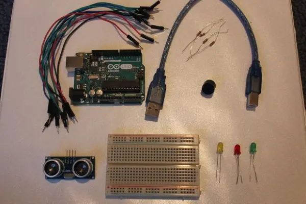
Step 1: Assemble Materials
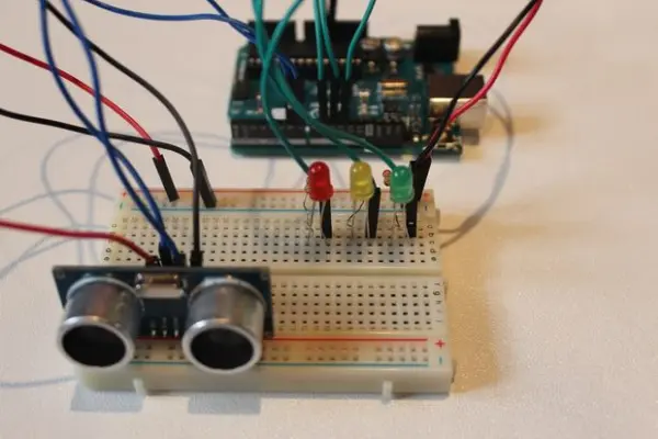
Step 2: Setup
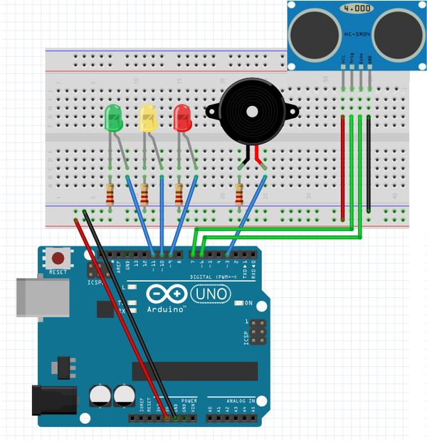
Attach a red wire from the 5V pin on the Arduino to the positive segment of the breadboard. Establish a connection with a black wire from the GND pin on the Arduino to the negative segment of the breadboard.
For the components, use the following pins:
– Buzzer is connected to pin 7.
– On the Ultrasonic Sensor, link Echo to pin 3 and Trig to pin 2.
– LEDs are connected as follows: RedLED to pin 4, YellowLED to pin 5, and GreenLED to pin 6.
Connect the green wires to the LEDs by joining them in series with the positive side of the LED, while the negative side of the LED should be linked to the negative segment of the breadboard through a 220 ohm resistor.
Step 3: Assembly – Breadboard
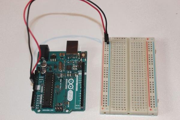
To begin, we’ll establish a connection between the 5V and GND pins on the Arduino and the breadboard. As previously noted, ensure that the wire connected to the 5V pin is linked to the positive section of the breadboard, and the wire connected to the GND pin is linked to the negative section of the breadboard.
Step 4: Assembly – Ultrasonic Sensor
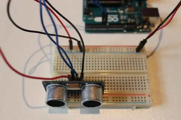
It’s time to set up the HC-SRO4 ultrasonic sensor! A useful suggestion is to position the ultrasonic sensor on the far right of the breadboard, ensuring it faces outward. To follow the setup image, establish a connection by attaching the GND pin from the ultrasonic sensor to the negative rail on the breadboard. Then, link the Trig pin on the sensor to pin 2 on the Arduino, and connect the Echo pin on the sensor to pin 3 on the Arduino. Lastly, connect the VCC pin on the ultrasonic sensor to the positive rail on the breadboard. If you encounter any confusion, consult the image above.
Step 5: Assembly – LEDs
The subsequent action involves linking the LEDs to both the breadboard and the Arduino. If necessary, I strongly advise you to refer back to the setup image in Step 2. Attaching the LEDs is a straightforward process with a lot of repetition involved. Let’s commence by connecting the Green LED. To achieve this, connect the anode (the longer leg) to pin 6 on the Arduino using a green wire and link the cathode (the shorter leg) to the negative channel on the breadboard using a 220 ohm resistor. Subsequently, repeat this procedure for the Yellow and Red LEDs. Ensure that you connect the anode (the longer leg) of the yellow LED to pin 5 on the Arduino and the anode of the red LED to pin 6. Upon completing these steps, your configuration should resemble the illustration above. Although resistors are not absolutely mandatory, I highly recommend using them.
Step 6: Assembly – Buzzer
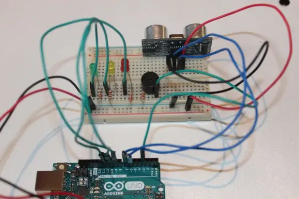
The final step in setting this up involves linking the buzzer with both the breadboard and the Arduino. This is a relatively straightforward aspect of the entire process. You only need to attach the lengthier pin of the buzzer to pin 7 of the Arduino using a green wire, and then link the shorter pin of the buzzer to the negative rail of the breadboard through a 220-ohm resistor.
Using a resistor to connect the shorter pin of the buzzer to the negative rail of the breadboard is strongly recommended. This practice significantly lowers the buzzer’s volume and extends its lifespan.
Code
Ultrasonic Security System
Source: Ultrasonic Security System