
Step 1: Project Presentation
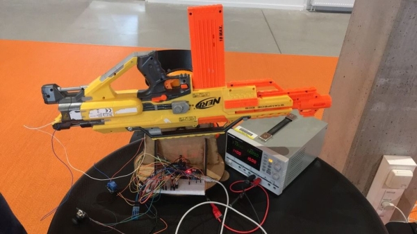
This project/instructables shows how to make a nerf gun operated by a remote control. The nerf gun is placed on a bracket which parts are 3D printed and laser cut. That way the nerf gun is able to stand by it self.
The nerf gun rotates and moves on the x- and y-axis which results in it being able to move up, down, left and right. However there is also a kind of a dimensional z-axis. It’s the “Fire” function which enables the nerf gun to shoot.
The nerf gun is connected to a Bluetooth module which communicates with a mobile app and therefore makes it possible to control the nerf gun via the app.
Step 2: Step 1: Equipments
Materials:
- 1 x Nerfgun turret
- 1 x Arduino Mega 2560 board (connected to a computer via USB)
- 1 x Breadboard
- Lots of jumpwires
- 1 x Power supply
- 1 x Relay
- 2 x Pololu a4988
- 2 x Nema 17 hybrid stepper motor 2 phase
- 2 x Ultrasonic sensor HC-SR02
- 1 x HC-05 bluetooth module
- 1 x Analog joystick controller breakout
- 3 x 1k Ohm Resistors or one 1k resistor and one 2k resistor.
Mechanical equipments:
- Some kind of fitting/holding,
- 4 x ball bearings
Step 3: Fablab
We’ve used fablab to make some mechanical equipments to the nerf gun. The goal was to make the nerfgun stand by itself and that is why we used Fablab.
In Fablab we designed, 3D-printed and lasercut some mechanical equipments which made it possible for the nerfgun to now stand by it self and, along with the Bluetooth communication, to work without any kind of physical human interaction.
The holder/fitting:
– A kind of a fitting
The fitting is 3D-printed and made so it fits the side of the nerfgun perfectly.
The outline/sketch of the fitting was created by a 3D scanner. Afterwards the outline got edited in vxelements before finally printing it, which took about 12 hours.
The rest of the mechanical equipments:
– Two toothed wheels.
The rest of the equipments is made out of wood. The sketches are made in respectively Illustrator and AutoCAD.
When the final sketches were done, it got laser cut.
Step 4: Step 4: How It Works
The first video shows how the nerf gun works using only the joystick.
The second videos shows how it works using android app which communicates with the bluetooth module.
Step 5: Pin Connection
2 x Nema 17:
- sx = pin 2 (step x-axis)
- dirx = pin 3 (direction x-axis.
- sy = pin 4 (step y-axis)
- diry = pin 5 (direction y-axis)
Ultrasonic sensor
- trigPin1 = 12
- echoPin1= 13
- trigPin2 = 51
- echoPin2 = 49
Analog Joystick:
- Analog x-axis = A0
- Analog y-axis = A1
- Switch = pin 6
Relay:
- Relay = pin 7
Bluetooth:
- Bluetooth_RXD = Arduino_TXD
- Bluetooth_TXD = Arduino_RX
Step 6: Connect the Equipments

Insert the ultrasonic sensor into the breadboard.
1) Connect the the GND on the ultrasonic sensor to the GND Arduino pin.
2) Connect the VCC to the 5V Arduino pin.
3) Connect the trig to pin 51 on the Arduino Board.
4) Connect the echo to pin 49 on the Arduino Board.
Analog Joystick:
1) Connect the VCC and GND pins respectively to the positive and negative rail on the breadboard.
2) Connect the V pin to A1 on the Arduino Board, and the H pin to A0 on the Arduino Board.
3) Furthermore, the A1 pin needs to be connected to the Nema 17 stepper too
Pololu a4988:
1) Connect the Nema 17 to the motor pin on the pololu.
2) Connect the Step pin to an Arduino Pin.
3) Connect the Direction pin to an Arduino Pin.
4) Connect it to respectively 12V and GNd and 5V on the Arduino.
Bluetooth:
1) Connect the VCC and GND pins respectively to the positive and negative rail on the breadboard.
2) Connect the Bluetooth’s RXD pin to the TXD Arduino pin (use the resistors here to avoid burning the module)
3) Connect the Bluetooth’s TXD pin to the RXD Arduino pin.
Connecting the Nerfgun to the circuit:
1) Connect the positive and negative wires to the relay.
2) Connect the relay to the power supply.
Step 7: Fritzing
Step 8: Code Breakdown
Parts of the code explained:
if(Serial.available() > 0)  <br>  {
    state = Serial.read();      //Read the incoming data and store it into variable Incoming_value
    Serial.print(state);        //Print Value of Incoming_value in Serial monitor
    Serial.print("\n");        //New line
  }
Here it reads the incoming data from the bluetooth module and saves it in the variable “state”.
//Read the joystick.<br>  joyx = analogRead(A0);
  joyy = analogRead(A1);
  notPressed = digitalRead(inPressed);

  if ( notPressed == 0 || state == 8)
  {
//      Serial.print(notPressed);
      digitalWrite(relay, HIGH);
  }
  else{
    digitalWrite(relay, LOW);
  }
This part of the code reads the bluetoothmodule. If the joystick is being pressed (notPressed == 0 ) and the bluetooth “fire” button is (state == 8), the relay will activate and cause the nerf gun to shoot. Otherwise it will stay inactive.
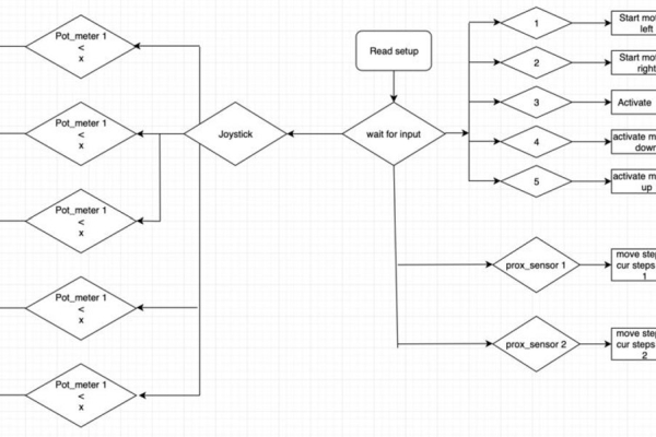
The steppermotor moves according to the joystick direction/position.
if (joyx < 550 && joyx > 450 || joyy < 550 && joyy > 450  )<br>  {
    digitalWrite(dirx, LOW);
    digitalWrite(diry,LOW);
    digitalWrite(sx, LOW);
    digitalWrite(sy, LOW);
//    digitalWrite(relay, LOW);
When the joystick is in this position the axises won’t move and the relay will stay inactive.
//The x, axis will start and move to the left<br>  if (joyx > 550 || state == 1 )
  {
    digitalWrite(dirx, LOW);
    digitalWrite(sx, HIGH);
    delay (fart);
    digitalWrite(sx, LOW);
    delay(fart);
    curstepx++;
  }
  //The axis will start moving right.
  if (joyx < 450 || state == 2)
  {
    digitalWrite(dirx, HIGH);
    digitalWrite(sx, HIGH);
    delay (fart);
    digitalWrite(sx, LOW);
    delay(fart);
    curstepx--;
  }
  // The y-axis will start moving.
  if (joyy > 550 || state == 4)
  {
    digitalWrite(diry, LOW);
    digitalWrite(sy, HIGH);
    delay (fart);
    digitalWrite(sy, LOW);
    delay(fart);
    curstepy++;
  }
  // The y-axis will start moving up or down.
  if (joyy < 450 || state == 5)
  {
    digitalWrite(diry, HIGH);
    digitalWrite(sy, HIGH);
    delay (fart);
    digitalWrite(sy, LOW);
    delay(fart);
    curstepy--;
  }
Depending on the position/direction of the joystick, the motors will either move up, down, right or left. The code also shows that depending on the input from the android app, the motors will move according to that.
This is the code for the sensors.
// long duration1, distance1;<br>//  digitalWrite(trigPin1, LOW);  // Added this line
//  delayMicroseconds(2); // Added this line
//  digitalWrite(trigPin1, HIGH);
//  delayMicroseconds(10); // Added this line
//  digitalWrite(trigPin1, LOW);
//  duration1 = pulseIn(echoPin1, HIGH);
//  distance1 = (duration1/2) / 29.1;
////
////   if (distance1 < 10 || distance1 <= 0){
////    Serial.println("SHOOT!");
////    digitalWrite(relay, HIGH);
////    delay(1000);
////    digitalWrite(relay, LOW);
////
////  }
//    Serial.print("Sensor1  ");
//    Serial.print(distance1);
//    Serial.println("cm");<br>
This is for the first sensor which is placed at the nerf guns barrel. The sensor measure the distance, and if an object is within 10 cm, it will activate the relay and cause the gun to shoot at the target.
Code for sensor 2:
//long duration2, distance2;<br>//  digitalWrite(trigPin2, LOW);  // Added this line
//  delayMicroseconds(2); // Added this line
//  digitalWrite(trigPin2, HIGH);
//  delayMicroseconds(10); // Added this line
//  digitalWrite(trigPin2, LOW);
//  duration2 = pulseIn(echoPin2, HIGH);
//  distance2= (duration2/2) / 29.1;
//  if (distance2 <= 10 ){
//    Serial.println("BEHIND ME!");
//    for (i = 0; i < 100; i++) {
//    digitalWrite(dirx, LOW);
//    digitalWrite(sx, HIGH);
//    delay (fart);
//    digitalWrite(sx, LOW);
//    delay(fart);
//    curstepx++;}
//
//    }
//
//    }
//
//  else {
//    Serial.print("Sensor2  ");
//    Serial.print(distance2);
//    Serial.println("cm");
//  }
This part basically works like the part for sensor 1. The only difference is, it doesn’t activate the relay. It reacts when an object is within 10 cm reach.
Be aware that some parts of the code doesn’t work properly, and that is why they are put as comments. We’re still trying to debug the program and solve the errors. It may have something to do with the way the wires are connected, if the wires are a bit unstable it’ll result in errors and make the hardware sep up work incorrectly. Or if the code isn’t correct it’ll also result in the hardware working differently from what is originally planned/thought.
Source: UCL – Embedded – NerfGunTurret