Summary of Tutorial 19: Arduino Dice Circuit And Sketch Using A 7-Segment Display
This tutorial guides users in building an interactive Arduino dice using a 74HC595 IC and a common cathode 7-segment display. The device features shake, throw, and number display animations triggered by holding and releasing a push button. By utilizing the shift register, the project interfaces the display with only three Arduino digital pins, optimizing resource usage while providing visual feedback for dice rolls.
Parts used in the Arduino Dice:
- 10k resistor
- 470 Ω resistors
- 100n capacitor
- 74HC595 IC
- Common cathode 7-segment display
- Push button switch
In this tutorial you will build a dice that is shaken by holding the button in and thrown by releasing the button. The shake, throw and number thrown are animated and displayed on a seven segment display.
A 74HC595 IC is used to interface the 7-segment display to the Arduino, using only 3 Arduino digital pins.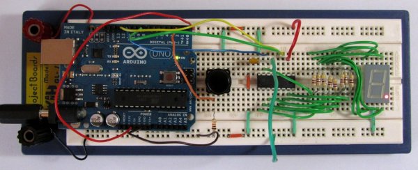
Prerequisites
Know how to use a DIP IC, e.g. from tutorial 17 – Electronic Dice. Read about seven segment displays.
Components
| Qty | Part | Designator | Notes | Type |
|---|---|---|---|---|
| 1 | 10k resistor (brown – black – orange) | R9 | 1/4W 5% or better | Resistors |
| 8 | 470 Ω resistors (yellow – violet – brown) | R1 to R8 | ||
| 1 | 100n capacitor | C1 | Non-polorized capacitor | Capacitor |
| 1 | 74HC595 | U1 | 74HC595 IC (16 pin DIP) | Semiconductors |
| 1 | Common cathode 7-segment display | S1 | Common cathode 7-segment display, e.g. DMR14C from SunLED, or similar | |
| 1 | Push button switch | SW1 | Can also use a wire link to simulate a switch | Switch |
Circuit Diagram
The circuit diagram is shown below. The seven segment display could have been directly interfaced to the Arduino, but by using the 74HC595, only 3 Arduino pins are used.
Find more information about interfacing the 74HC595 IC to the Arduino in the Serial to Parallel Shifting-Out with a 74HC595 article from the Arduino website. The circuit diagram uses the same Arduino pins as this article and the switch is wired the same as the Arduino Button example.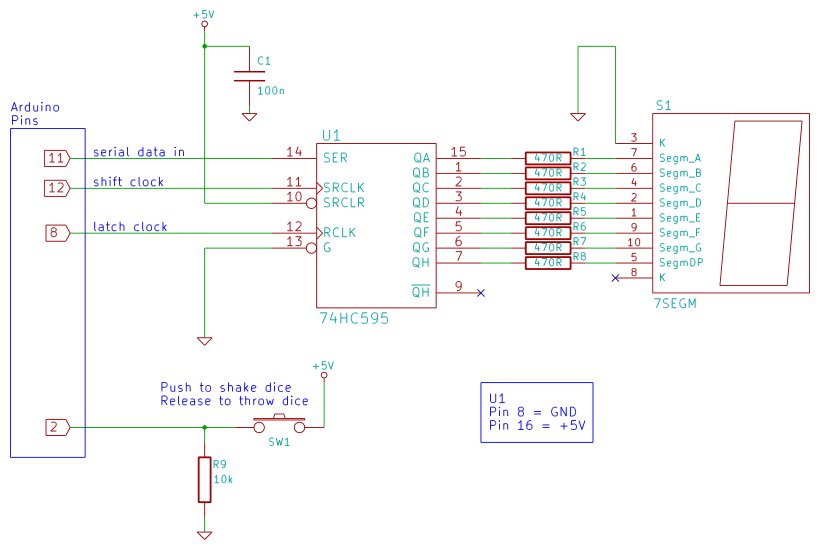
The suggested sequence for building the circuit is:
- Insert the 74HC595 IC into the breadboard and hook up its power and ground pins to the top and bottom breadboard rails.
- Insert and wire up capacitor C1 (100n).
- Insert the 7-segment display.
- Insert the 470 ohm resistors.
- Wire the resistors to the 7-segment display.
- Wire the resistors to the 74HC595 IC.
- Wire pin 10 of the IC to 5V.
- Wire pin 13 of the IC to GND.
- Connect the push button switch and R9.
- Wire the switch to the Arduino.
- Wire the 74HC595 to the Arduino
For more detail: Tutorial 19: Arduino Dice Circuit And Sketch Using A 7-Segment Display
- How is the dice shaken and thrown?
The dice is shaken by holding the button in and thrown by releasing the button. - What components animate the shake and throw?
The shake, throw, and number thrown are animated and displayed on a seven segment display. - Why use a 74HC595 IC in this project?
A 74HC595 IC is used to interface the 7-segment display to the Arduino using only 3 Arduino digital pins. - What type of 7-segment display is required?
The project requires a common cathode 7-segment display, such as the DMR14C from SunLED. - Can a wire link be used instead of a switch?
Yes, the push button switch can also be replaced with a wire link to simulate a switch. - Which specific resistors are needed for the circuit?
The project needs one 10k resistor and eight 470 Ω resistors. - What is the recommended sequence for building the circuit?
The suggested sequence starts with inserting the 74HC595 IC, followed by the capacitor, display, resistors, and finally the switch and Arduino connections. - Where can I find more information about the 74HC595 interfacing?
More information is available in the Serial to Parallel Shifting-Out with a 74HC595 article from the Arduino website.