Summary of Tree Climbing Robot using Arduino
Summary: An Arduino-controlled tree-climbing robot was built with two legged segments joined by an extendable spine. Each segment has four spiked legs driven directly by high-torque geared DC motors; a threaded-rod linear actuator extends/retracts the spine. Three L298 H-bridge motor drivers, rotation sensors, limit switches, and a multi-battery power system control the motors and sequencing to climb trees like an inchworm.
Parts used in the Tree Climbing Robot:
- Arduino Uno (any will work)
- 3x L298HN Dual Full Bridge chips
- 2.5 x 3.125 Perf Board
- Terminal strips
- 22AWG solid core wire
- 3x Aluminum heatsinks
- Thermal paste
- 9V battery (for Arduino)
- Approximately 12V LiPo or Li-ion battery (modified laptop battery)
- 5V regulator
- 9V battery clip
- Barrel connector
- 4x 7 RPM gear motors
- 4x thin linear trim pots (rotation sensors)
- DPDT toggle switch (power switch)
- SPDT slide switch (user input)
- 2x mini snap action switches (limit switches)
- 3x 10K resistors (pull down)
- Headers
- Signal wire (old IDE cables)
- Heat shrink tubing
- 12' 3/4 x 1/8 Aluminum bar
- 6 x 3 acrylic sheet
- 6x standoffs with screws
- 1' threaded rod and 1/2" nut
- 2x 1' x 3/16" steel rod
- 1' x 3/16" I.D. brass tubing
- 4x 5mm aluminum universal mounting hub
- Pack of large T pins
- 4x 3/32 screws (for motors)
- Assortment of 4/40 screws and nuts
- Assorted hex screws and nuts
- 4x Bic pens (plastic shafts for pot mounts)
- 4x locknuts
- 5 minute epoxy
- Sheet metal scraps
- Stick on Velcro
- Hard drive reading head bearing
- 3/4" plastic angle
- Electrical tape
- Zip ties
- Drill / drill press
- Hacksaw
- Soldering iron
- Pliers
- Allen wrench
- Screwdrivers
- Wire strippers
- C clamp
- Ruler
- Files
- Optional: bench PSU, multimeter, breadboard
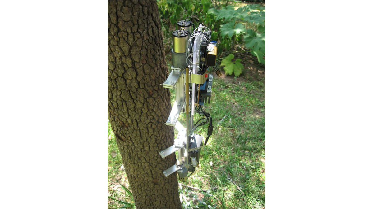
After I got comfortable programming and building with an Arduino, I used my newly acquire microcontroller skills to build a robot. Using a microcontroller, four high-torque DC gear motors, spiked legs, a linear actuator, rotation sensors, and 3 L298 H-bridge circuits, this robot can climb up trees of varying diameter. The very long build log follows.
I started out by creating a basic design in Sketchup. The robot was to consist of two segments, joined by a spine which could be extended or retracted. Each segment would have four legs with very sharp points as feet. To climb, the legs on the top segment would pinch together and the sharp feet would dig into the bark, securing the robot. Then the spine would be retracted, pulling up the bottom segment. The legs on the bottom segment would then grip the tree, and the top segment would release. Finally, the spine would extend, pushing the top segment upwards, and the process would repeat. The climbing sequence is similar to the way an inchworm climbs.
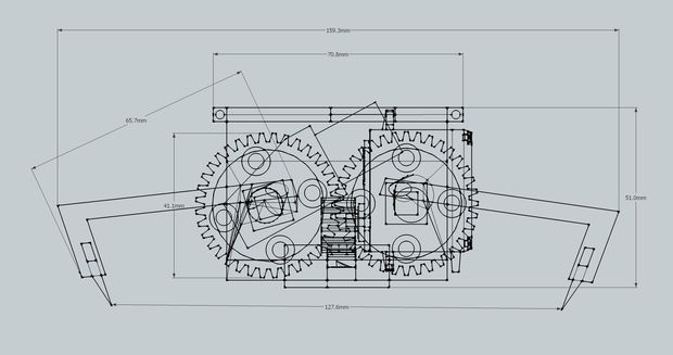
In my original design (show in the images above), all four legs in each segment were controlled by one highly geared down motor. I decided to ditch this idea for a few reasons. Firstly, I could not find the type of spur gear needed to mesh the legs together. Also, with all the legs linked together, the robot would have a hard time gripping uneven surfaces. Finally, I decided that the robot would be much easier to build if the motors drove the legs directly.
The other significant change I made from my original design was the way the spine worked. In my model, I used a rack and pinion type gearing system to extend and contract the spine. However, I could not find the necessary parts to build such a system, so I ended up using a threaded rod coupled to a motor to actuate the spine.
Original design:
Tools and Materials:
Microcontroller
- Arduino Uno (any will work)
- 3X L298HN – these can be gotten for free as samples from ST
- 2.5″ x 3.125″ Perf Board
- Terminal Strips
- 22AWG Solid core wire
- 3X Aluminum heatsinks (I cut in half an old northbridge heatsink)
- Thermal paste
Power
- 9V Battery (to power the Arduino)
- Approximately 12V LiPo or Li-ion battery (I modified a laptop battery, so I did not even need to buy a charger)
- 5V regulator (To regulate power to the motor controller logic circutry)
- 9V Battery clip
- Barrel connector (Must fit the Arduino power connector)
Other Electronics
- 4X 7 RPM Gear Motor (These power two legs each)
- 4X Thin linear trim pots (Rotation sensors for the legs)
- DPDT Toggle switch (Power switch)
- SPDT Slide switch (User input)
- 2X Mini Snap Action Switch (Limit switch)
- 3 10K resistors (Pull down)
- Headers
- Signal Wire (Old IDE cables work really well, and let you organize your wires easily)
- Heat Shrink Tubing
Hardware
- 12′ 3/4″ x 1/8″ Aluminum Bar (These come in 6′ lengths at my local hardware store)
- 6″ x 3″ acrylic sheet (Electronics are mounted to this)
- 6x Standoffs with screws
- 1′ Threaded rod and corresponding 1/2″ nut
- 2X 1′ x 3/16″ steel rod
- 1′ x 3/16″ I.D. Brass Tubing
- 4X 5mm Aluminum Universal Mounting Hub
- Pack of large T Pins
- 4X 3/32 screws (to mount the motors)
- An assortment of 4/40 screws and nuts
- Assorted hex screws and nuts
- 4X Bic pens (I used the plastic shafts to fix the pots on the legs in place)
- 4X Locknuts
- 5 Minute epoxy
- Sheet metal scraps (For spacing and mounting things. Bits of Meccano work well)
- Stick on Velcro (For holding on the batteries)
- Hard Drive reading head bearing
- 3/4″ Plastic angle
- Electrical Tape
- Zip Ties
Tools
- Electric Drill / Drill press (As well as a lot of bits)
- Hacksaw
- Soldering Iron
- Pliers
- Allen wrench
- Assorted screwdrivers
- Wire Strippers
- C Clamp (These can be used to make nice 90 degree bends in the aluminum)
- Ruler
- Files
Nonessential
- Bench PSU
- Multimeter
- Breadboard
Circuit:
The motor controller I built for this robot is based off the L298HN Dual Full Bridge chip. To use the chip, I followed the guide here. To start out, I placed all the components on a piece of perf board, to figure out the layout. With this chip, each motor requires three inputs to work: an enable signal and two input signals. The enable signal is used to control the motor speed with PWM, but since I did not need to control PWM, I just wired all the enable pins in parallel to a 5V line when I hooked the controller up to the Arduino. Once I figured out the layout, I soldered all the components in place, and made connections with 22AWG solid core wire. Finally, I spread some thermal paste on the back of the L298’s, and screwed on the heatsinks. The particular heatsinks I used were made by cutting in half a northbridge heatsink from a computer motherboard, and drilling and tapping a hole for the screw. They are probably much larger than needed, but there is no harm in having over sized heatsinks. A higher resolution image of the labeled board can be found here.
- Arduino Uno (any will work)
- 3X L298HN – these can be gotten for free as samples from ST
- 2.5″ x 3.125″ Perf Board
- Terminal Strips
- 22AWG Solid core wire
- 3X Aluminum heatsinks (I cut in half an old northbridge heatsink)
- Thermal paste
For more detail: Tree Climbing Robot using Arduino
- What microcontroller was used?
The project used an Arduino Uno (any will work). - How is the spine actuated?
The spine is actuated by a threaded rod coupled to a motor. - What motor drivers were used?
Three L298HN Dual Full Bridge chips were used to drive the motors. - How are the legs driven?
Each leg is driven directly by high-torque geared DC motors rather than linked gearing. - What sensors detect leg rotation?
Thin linear trim pots were used as rotation sensors for the legs. - What batteries power the robot?
A 9V battery powers the Arduino and an approximately 12V LiPo or Li-ion battery powers the motors. - How were the L298 chips cooled?
Aluminum heatsinks were attached with thermal paste; heatsinks were cut from a northbridge heatsink. - Does each motor require PWM inputs on the L298?
Each motor needs an enable and two input signals; the enable pins were tied to 5V since PWM was not needed.