Summary of Traffic light and pedestrian crossing implemented with an Arduino
This article details an Arduino-based traffic light and pedestrian crossing system modeled after a local crossing. The project uses an Arduino Mega2560 for development, aiming for a smaller implementation later. It employs a state machine triggered by interrupts to manage light cycles, ensuring safety with a default red-light startup. Hardware includes LEDs sharing a 220-ohm resistor and a button pulled low with a 47K ohm resistor. Diagrams were created using Fritzing software.
Parts used in the Traffic Light and Pedestrian Crossing:
- Arduino Mega2560
- LED lights
- 220 ohm current-limiting resistor
- Call button
- 47K ohm pull-down resistor
- Alligator clips
- Fritzing software
This video shows the Traffic light and pedestrian crossing I’ve implemented with an Arduino. It’s a reproduction of the crossing near my home, timings taken from a video of it.
Incidentally, I produced the diagrams for this using a product called Fritzing. It’s a nifty piece of software that allows you to draw a breadboarded version of your circuit, lay out the circuit schematic and then automatically design the artwork for a etched circuitboard. I haven’t experienced the latter, because of an autoroute bug in version 0.8 of Fritzing.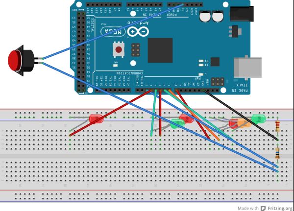 I exported the images as SVGs from Fritzing and discovered that WordPress won’t allow them to be uploaded because of security issues; presumably the ability to include JavaScript inside a SVG for animation (etc). So then I exported as PNG, the lossless format. One of the two images wouldn’t upload, but was acceptable to WordPress after scaling down. I started out publishing on the web using notepad and FTP, and look where I am now.
Hardware
I’ve been using an Arduino Mega2560 as the development environment but I’m targeting something smaller for implementation. The code compiles (on the bulky Mega instruction set) to 3.5Kb, so I’m satisfied that as things stand I’m not going to blow any memory budget.
The LED lights all share a single 220 ohm current-limiting resistor, and the call button is pulled low with a 47K ohm resistor to prevent the input pin from floating all over the shop when the button isn’t pressed.
You may notice that the video doesn’t exactly match the diagram. That’s because it’s built out of bits and bobs I had lying around. The ~200-ish Ohm resister had leads that wouldn’t insert into the breadboard. Thus, alligator clips all over the place.
Software
The light cycle is handled with a state machine; the flashing of lights is effected via state changes. The state machine is triggered by interrupts; the ISRs (Interrupt Service Routines) are lightweight, with the “heavyweight” processing for the state machine occurring in response to changes made in the ISRs. To minimise the processing load in the buttonpress ISR a test has been cached in a variable. The timer ticks over every half second, giving the state machine a half-second resolution – which seems to match what happens in the real world.
The state machine is initialized into a safe state of having the traffic face a red light, and the pedestrians facing the flashing red man. That means if the system restarts in the middle of a crossing cycle, no one gets killed.
Although the timer is fired via an interrupt, it won’t fire during a delay() so the delay in the main loop is very short.
Although the environment gives an opportunity to develop an OOP solution, their wasn’t any clear need for that level of abstraction, and microcontrollers tend to feel the additional cost of indirection. For example, accesses to members of the state were costly in terms of instructions and lead me to consider using multiple single dimension arrays, accessed by pointer.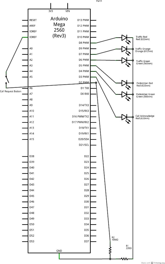 #include <TimerOne.h> //#define DEBUG /* Simulate a pedestrian crossing An Australian pedestrian crossing has three traffic control lights, two pedestrian control lights and a light to acknowledge “call requests” (i.e. pressing the crossing button). The traffic control lights cycle red -> green -> amber, solid in all. The pedestrian control lights cycle red -> green -> flashing red. The crossing button lights up the call request light, which stays lit until the pedestrian control light turns green. Once the traffic control light turns green, it stays that way for some time before it will yield to a call request. This is to ensure the road is not continuously blocked servicing pedestrian crossing needs. This code responds to two events: the passage of time and the pressing of the call request button. Outside of responding to these events the program has no secondary task. To optimize the performance of the CPU in its secondary task, the primary tasks occur in response to interrupts. */ // Pin allocation: const int CallbuttonPin = 2; // the “I want to cross” button const int lightCallAcknowledge = 3; // the light that says “you pressed the button” const int lightGreenMan = 4; // Pedestrian “walk now” const int lightRedMan = 5; // Pedestrian “Do not start walking” const int lightGreen = 6; // Traffic go const int lightAmber = 7; // Traffic stop if safe const int lightRed = 8; // Traffic stop const int timerPin1 = 9; // lost to timing, can’t be used for IO const int timerPin2 =10; // lost to timing, can’t be used for IO const int onBoardLED = 13; // on board, can be over-ridden or even cut
For more detail: Traffic light and pedestrian crossing implemented with an Arduino
- What hardware is used as the development environment?
The author has been using an Arduino Mega2560. - How are the LED lights powered?
All LED lights share a single 220 ohm current-limiting resistor. - Why is a 47K ohm resistor used?
It pulls the call button input low to prevent the pin from floating when not pressed. - What software was used to create the diagrams?
The diagrams were produced using Fritzing software. - How does the system ensure safety upon restart?
The state machine initializes with the traffic facing red and pedestrians facing a flashing red man. - What resolution does the timer provide?
The timer ticks every half second, giving the state machine a half-second resolution. - Can the code be compiled for a smaller microcontroller?
Yes, the code compiles to 3.5Kb on the Mega instruction set, fitting within memory budgets for smaller targets. - Why were SVG files not uploaded to WordPress?
WordPress blocked them due to security issues regarding potential JavaScript inclusion inside the SVG.