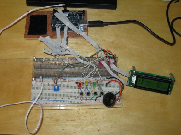
Total Recall is a Simon based game for the Arduino. Your basic Arduino Simon Game consists of 4 buttons, 4 LEDs, an Arduino, some code and maybe a speaker and sound effects. Total Recall takes things a step further by adding an LCD display and offering 1 and 2 player game modes.
The 1 Player game is your basic Simon Game. I added 4 levels of difficulty to it by giving you options for how many rounds you want to play. Your then given a sequence of flashing lights to mimic. Each round adding an extra flash to the sequence. If you can complete the number of turns you win.
The 2 Player game puts you head to head against a friend. The game starts with player one entering the first button into the sequence. The Sequence is then played back for player 2 to see. Then player 2 gets to mimic the sequence. If he gets it correct he gets the opportunity to add a button to the sequence. Then Player 1 gets the play back and tries to mimic the sequence. The game goes back and forth like this with the sequence getting increasingly longer till one player gets it wrong or you reach 99 turns in which case you’ve hit the max length of the sequence and the game is a draw.
Materials Needed:
- Arduino (I used a Nove)
- Bread Board
- Jumper Wires/Ribbon cables
- Red, Yellow, Green and Blue LEDs
- 4x 100 Ohm Resistors
- 4x Push Buttons
- Small Speaker
- Hitachi HD44780 based 16×2 LCD
- 5K Potentiometer
Step 1: Background
After posting Arduino Simon Says i started getting ideas for ways to improve the game. Whenever possible i like to simplify my code to reduce the amount of memory it uses. One of the things that really eats up memory in an Arduino sketch is using the Serial interface. Since the eventual goal is to get this game onto its own PCB and make it an actual portable game linking it to a computer to track your progress wasn’t going to be an option. Removing the Serial commands from the game dropped 2004 bytes from the compiled code. So to help me towards my goal of portability i decided to add an LCD display to the game.
Then i started thinking how i could make the game play even better. And what better way to make a game more fun then to play it with a friend. So i would need to come up with a menu system allowing you to choose between the 2 game types. I also wanted to make the original Simon game more interesting as well. So i decided it would be good to give people the option of how many turns they could shoot for. Nothing like giving people a goal to shoot for to make things more interesting.
Now a checklist of ideas was starting to come together.
- Add LCD display
- Create difficulty options for single player game
- create 2 player game
All these ideas raised many questions.
Step 2: Adding the LCD
Now i was ready to figure out where to connect my LCD. Considering most of my Digital I/O pins where taken i had to figure out where i was going to connect the LCD. I wanted to keep as many of the LCD wires as close together as possible. This makes it a bit easier to troubleshoot any problem. I also didn’t want to move the LEDs and Buttons around. This would just add to the headach of updating the code. So i decided to place the LCD on the Analog In pins. The Analog Pins can be used as Digital I/O pins. The are designated as follows:
- Analog 0 = Digital 14
- Analog 1 = Digital 15
- Analog 2 = Digital 16
- Analog 3 = Digital 17
- Analog 4 = Digital 18
- Analog 5 = Digital 19
I couldn’t put all the LCD pins across the Analog pot cause i still need Analog pin 0 for randomization of the single player game. So the LCD is connected as follows:
- RS pin to D13
- E pin to D12
- D4 pin to D16
- D5 pin to D17
- D6 pin to D18
- D7 pin to D19
- V0 tied to a pot to control brightness
- Grd and R/W tied to ground
- Vcc to +5V
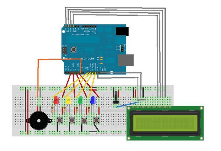
You can refer back to the Arduino Simon Says Instructable concerning the setup of the rest of the hardware. The only change made was moving the speaker over to pin 6. I hope the Fritzing image helps to clear up any confusion there might be in the wiring. I went ahead and attached the Fritzing file if you need a better look at the diagram. You can also refer back to my Custom Large Font For 16×2 LCDs for more information about setting up a Hitachi HD44780 based 16×2 LCD on the Arduino.
- Arduino (I used a Nove)
- Bread Board
- Jumper Wires/Ribbon cables
For more detail: Total Recall- Arduino Simon Says on steroids