I got my son a tiny whoop indoor FPV drone for Christmas, specifically an EMAX Tinyhawk II. We’ve had fun creating small obstacle courses in our basement, but one thing was missing – a timer so we could compare flight times.
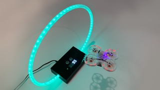
This instructable (my first) is for a drone gate with an automatic timer that can be used at the start and end of the course. When the drone passes through the gate at the start of the course, a timer starts and continues until the drone passes through the gate again at the end of the course.
Since we’re using an Arduino as the brains of this project, we decided to add an RGB LED strip in a circle that the drone flies through. The LEDs change colors every ten seconds during the race that the pilot can see in their peripheral vision. If the race ends with a new record time, the LEDs show a chaser pattern. A long press of the reset button saves the current race time as the new record to beat.
Before going any further, let’s see this drone gate in action…
Step 1: Electrical Components
Below are the electrical components we used:
- Arduino Nano
- HC-SR04 ultrasonic distance sensor
- Adafruit 4-digit 7-segment display w/I2C backpack
- WS2812B individually addressable RGB LED strip (2M, 120 LEDs, 5V)
- Push button
- 1000µF capacitor
- 470-ohm resistor
- 10K-ohm resistor
- 5V power supply
- DC power adapter
- Micro USB cable
Step 2: Other Supplies
Below are additional supplies we used to construct the circuit and actual gate:
- Soldering iron
- Jumper wires
- Heat-shrink tubing
- Black plexiglass
- Drill press with paddle bits
- Jigsaw with plexiglass blade
- Hot glue gun
- ½” OD plastic tubing
- 1×2 poplar painted black
- Wood glue and nails
Step 3: Hardware
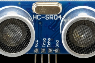
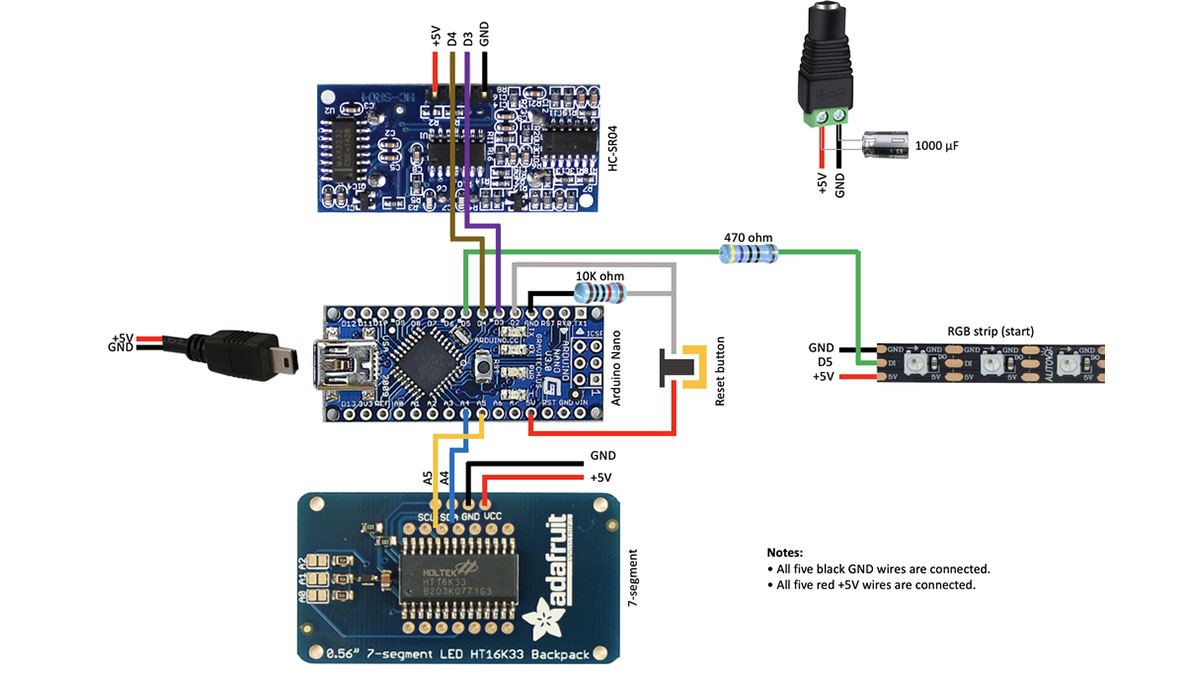
When setting out to build this drone gate, we weren’t sure what to use to detect the drone as it passes through the gate. We ended up using an HC-SR04 ultrasonic distance sensor – a common sensor often used in robotics to measure distance. This sensor has two pins that need connected to the Arduino – trigger and echo. We decided to connect these to digital input pins D4 and D3, respectively.
For displaying the race time and to keep things simple, we decided to use an Adafruit 4-digit 7-segment display w/I2C backpack. This display uses serial communications to update the display and is only connected to the two I2C pins on the Arduino Nano – A4 (data) and A5 (clock).
We used a narrow (5mm) 2-meter RGB LED strip that we folded in half onto itself so that the LEDs point both up and down. This LED strip is passed inside plastic tubing to hold its shape as a circle to fly the drone through. We connected the RGB LED strip to pin D5 on the Arduino using a 470-ohm resistor. We also added a 1000µF capacitor to the input power. The resistor and capacitor are recommended best practices for connecting RGB LED strips.
A simple push button is used to reset the timer back to zero. It can also be long pressed to store the displayed time as the record time to beat. We connected the reset button to pin D2 on the Arduino with a 10K ohm pull-down resistor to ground.
To power this project, we used a 5V power supply and female DC power adapter with terminal screws. The RGB LED strip has too many LEDs to be powered from the Arduino directly, so it’s wired directly to the power adapter. To power the Arduino, we decided to use an old micro-USB cable we had laying around. We soldered the 5V and GND wires of all the components together with the power and micro-USB cable and protected the connections with heat shrink tubing.
Step 4: Wiring Diagram
Step 5: Software
The software for this project is relatively straight-forward. The main program loop checks for the presence of the drone within the gate and starts or stops the race timer. The elapsed time is updated on the 4-digit display with a max time of “999.9” seconds. The most complicated portion of the code is updating the RGB LED strip to indicate race progress. Because we used a 2-meter LED strip folded back on itself, the LEDs need to be mirrored so the LEDs facing up match those that are facing down.
The Arduino Nano’s built-in EEPROM is used to save the record flight time, triggered by a long press of the reset button. When the project is powered up, the previously saved record time is displayed as a reminder of the time to beat.
Step 6: Construction
Before we set out to build the drone gate, we tested everything out using a breadboard. Once we were confident that the electronics were functioning properly, we set out to build the gate itself.
We decided to use a 4”×7” piece of black plexiglass for the top of the gate base. It looks nice and clean and can be cut to accept the electrical components. We carefully measured and drilled holes for the HC-SR04 ultrasonic distance center near the center of the plexiglass. Below that, we cut a rectangle for the 4-digit 7-segment display using a jigsaw with a plexiglass blade. The last cut needed was a ¼” hole for the reset button. Once all the holes were cut out, we used a hot glue gun to secure the components to the plexiglass from the underside.
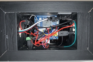
Next, we wired up all of the electrical components to the Arduino Nano. We positioned the Arduino Nano behind the HC-SR04 ultrasonic sensor and used a piece of double-face tape to keep the two components from touching. To simplify connecting the RGB LED strip, we cut the “output” connector off the end of the RGB LED strip and soldered its connections with the Arduino and power. Now, the RGB LED strip can be easily plugged in and removed using this connector.
Next, we made a wooden frame out of a piece of 1”×2” poplar that we painted black to match the plexiglass. We added an extra piece of wood on each end to help secure the plastic tubing that will house the RGB LED strip. We drilled ½” holes at a slight upward angle in both ends of the frame to accept the plastic tubing. We drilled another hole in the back of the frame for the DC power adapter. Finally, we glued the wooden frame to the plexiglass.
The last step was to use the adhesive strip on the back of the RGB LED strip and fold it in half onto itself. The RGB LED strip can then be passed through plastic tubing to form a circle over the base of the gate and connected to the connector that was cut from the end. The tubing itself is held in place only with friction so it can shift freely if the drone flies into it.
Step 7: Improvements
This project has been a lot of fun and makes flying our tiny whoop drone even more fun and competitive, but it’s not perfect. There is one flaw we’ve noticed with this project…
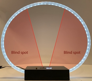
The gate itself has blind spots that the HC-SR04 ultrasonic sensor just can’t “see”. These blind spots are essentially the lower corners of the gate itself where it’s possible to pass through with no part of the drone passing over the distance sensor (the blind spot photo looks worse than it actually is). This could be overcome by adding multiple sensors, but we’ve simply learned to fly down the center of the gate – it rewards good piloting skills.
Source: Tiny Whoop Drone Gate With Timer