Summary of Timer With TM1637 and Arduino
This article details a compact, programmable countdown timer suitable for domestic and industrial use, featuring a 1 to 9999-second range, memory functionality, and acoustic/optical alerts. Constructed around an Arduino Nano and TM1637 display, the project utilizes a relay to control loads and includes a rotary encoder for time setting. The build process covers sourcing components from AliExpress or workshops, designing PCBs via KiCad, and assembling the module with plexiglas casing.
Parts used in the Programmable Countdown Timer:
- Arduino Nano
- TM1637 LED Display
- BC547 Transistors (2 pcs)
- 1N4148 Diode (1 pc)
- Round 5mm LEDs (2 pcs)
- 78M05 Voltage Regulator (1 pc)
- 15K/0.125W Resistors (2 pcs)
- 1k/0.25W Resistor (1 pc)
- 10uF/16V Capacitor (1 pc)
- Female Strip Connectors (3 pcs)
- Knobs (2 pcs)
- Screws, nuts, and spacers
- Plexiglas sheet (2.5 mm thick, 11x11 cm)
- Relay K1
- Buzzer BZ1
- Switches SW1 and SW2
- 12V / 500mA Power Supply
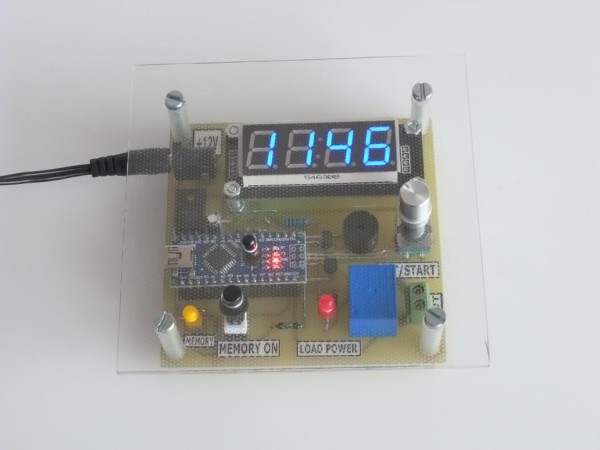
This timer is useful in both domestic and industrial applications. It is a countdown timer programmable in the range of 1s …. 9999s.
During this time, the load is powered by a relay on the board.
For repeated timings, it is possible to memorize the timing duration (MEM LED on).
The end of the period time is signaled acoustically with a Beep and optically by turning off the LOAD POWER LED.
In the first video you can see briefly how to program the timer (time setting):
For the beginning, an unsuccessful setting was made. This is solved with Reset on Arduino, the timer reaches zero and a new setting is made with rotary encoder at 13 s. The procedure is described in Step5.
The second video shows how the timer works while the load is powered ( the LOAD POWER LED is on). At the end of the period, the load is not powered, the LED goes out and because it worked with MEMORY ON pressed (LED MEMORY on) a new timer resumes from 13s, without the need for a new procedure for setting of time.
It is a compact module, not very big and can be easily made.
.
Supplies:
The modules and electronic components are bought from AliExpress at low prices. The mechanical materials can be found in our own workshop.
PCB can be made in your own workshop or can be ordered at the factory. There are all the necessary data for this.
Step 1: Gathering Materials and Tools
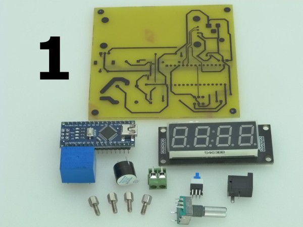
The main modules and electronic components can be found in photo1.
To these are added:
-BC547 -2 pcs.
-1N4148 -1 pc.
-LED round, 5mm – 2 pcs.
-78M05 -1 pc.
-15K/0.125W -2 pcs.
-1k/0.25W -1 pc.
-10uF/16V -1 pc.
– strip connector female -3pcs.
– knobs -2 pcs.
– Screws, nuts, spacers.
– Plexiglas 2.5 mm thick, 11X11 cm. recovered from the screen of an old LCD TV. -1pc
-Solder tin tools
-Pliers for cutting component terminals.
-Digital multimeter.
-Mechanical tools for plastic cutting, drilling, screwdrivers.
-Lust for work.
Step 2: Schematic Diagram
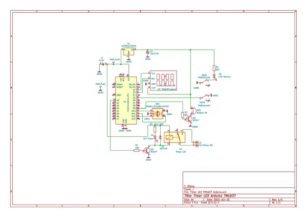
The wiring diagram is built around the Arduino Nano, which displays the information on the TM1637 LED display.
SW1 gives the necessary impulses to enter the time duration information.
On pin 19 Arduino we have the control voltage for the relay K1 (through Q1), which supplies the load during the delay and lights the LED D1.
Pin 12 Arduino commands Buzzer BZ1 through Q2 at the end of the timer, for 1s.
Pressing SW2 involves memorizing the delay time, D3 lights up.
The power supply of the module is made with 12V / 500mA at J1.
CI U1 (78M05) supplies the LED display and BZ1 separately with 5V.
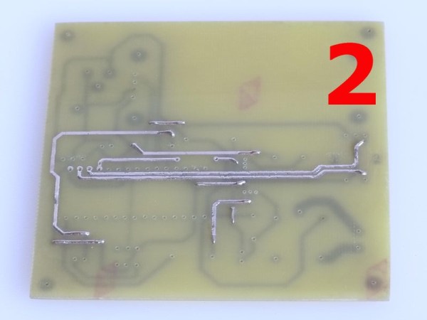
Step 3: Making PCB
At the address:
https://github.com/StoicaT/Timer-with-TM1637-and-A…
there are details of the PCB execution and other details of the project.
The PCB project is made in KiCad, a program that can be found for free on the Internet. Here are all the details needed to make PCB in your own workshop.
The program also easily generates the necessary Gerber files for factory PCB order.
In photo 4 you can see the overall sketch of the PCB, and in photo 2, 3 you can see the PCB made in my workshop.
.In the attached PDF file you will find the labels necessary to write the wiring if it is made in your own workshop.
If you order the PCB at the factory, the project has the inscriptions on it.
Step 4: Assembly and Putting in Function

Photos 6 … 8.0 show various phases of assembling the module, using soldering station with tin and cutting pliers for terminals. For safer orientation, the KiCad PCB drawing is used.
Photos 8 … 10.1 show the assembled module, exclusively the Plexiglas mask.
At this point it is good to put the module into operation.
After checking the correctness and continuity of the PCB routes (if it is done in our own workshop), it is supplied with + 12V and the + 5V voltage is checked.
If everything is OK, we upload the program into Arduino and should work.
Next, using the materials from photo 11, we make the final assembly, the result being that from photo 12.
One of the two Knobs will be used to reset the Arduino, the other for the MEMORY button.
Source: Timer With TM1637 and Arduino
-
How is the timer programmed?
The timer is programmed using a rotary encoder to set the time duration, which can be adjusted between 1 second and 9999 seconds. -
Can the timer repeat timings automatically?
Yes, by pressing the memory button, the timer memorizes the duration; when it finishes, it resumes from the saved time without needing reprogramming. -
What signals indicate the end of the timer period?
The end of the period is signaled acoustically by a beep and optically by turning off the LOAD POWER LED. -
How do you reset the timer if the setting fails?
An unsuccessful setting is solved by resetting the Arduino, after which a new time setting can be made with the rotary encoder. -
What voltage supplies the main module and the display separately?
The module is supplied with 12V at J1, while the 78M05 regulator provides 5V separately for the LED display and buzzer. -
Where can the necessary PCB data be found?
The PCB execution details and Gerber files are available on a GitHub repository linked in the article. -
What material is recommended for the casing mask?
A 2.5 mm thick Plexiglas sheet measuring 11x11 cm, recovered from an old LCD TV screen, is used for the mask.