Summary of Smart Pull-Up Bar
Summary: A 15-year-old maker built a Smart Pull-Up Bar that detects hand placement via a laser-LDR sensor, then plays music and dispenses a Tic Tac using an Arduino Nano and a servo. The project uses 3D-printed mounts and an enclosure, with optional PCB for compactness. Threshold adjustments via code or serial monitor tune sensor sensitivity.
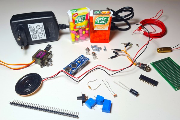
Parts used in the Smart Pull-Up Bar:
- Arduino Nano
- MG90S Servo Motor
- Laser Diode 9mm
- LDR (light dependent resistor)
- 0.5W Speaker 40mm
- 5V Power Supply
- DC Jack
- 1kΩ Resistor
- 100uF Capacitor
- Slide Switch 11mm x 6mm
- Wires
- 2 x M4 Screws and Nuts
- 4 x M3 Screws
- 5 x M2 Screws
- Some Tic Tacs
- Transparent plastic sheet
- Pull-Up Bar
- Filament (Prusament PETG used)
- PCB 6cm x 4cm (optional)
- Screw Terminals (for PCB, optional)
- Female Headers (for PCB, optional)
- Male Headers (for PCB, optional)
- 3D printer
- Soldering iron
Hello friends! My name is Nikolas and I am 15 years old. Today in this Instructable I’ll show you how to make a Smart Pull-Up Bar which, when you start doing Pull-Ups or Chin-Ups starts playing music in order to keep you motivated and after exercising for a certain period, a reward, a Tic Tac, in my instance gets dispensed! Make sure to watch the YouTube video above to see the Smart Pull-Up Bar in action and to follow the instructions from there if you prefer!
I originally thought of making this to motivate me to work out more, but it turns out I just wanted an excuse to eat more candy!
Supplies:
These are the components you’ll need:
- Arduino Nano (UK Here)
- MG90S Servo Motor (UK Here)
- Laser Diode 9mm (UK Here)
- 0.5W Speaker 40mm (UK Here)
- 5V Power Supply (UK Here)
- DC Jack (UK Here)
- LDR (UK Here)
- 1kΩ Resistor (UK Here)
- 100uF Capacitor (UK Here)
- Slide Switch 11mm x 6mm (UK Here)
- Some Filament (I used Prusament PETG)
- Wires (UK Here)
- 2 x M4 Screws and Nuts
- 4 x M3 Screws
- 5 x M2 Screws
- Some Tic Tacs
- A transparent plastic sheet you can cut
- And of course a Pull-Up Bar (UK Here)
If you decide to build a PCB as I did you’ll also need:
- PCB 6cm x 4cm (M2 Holes 55mm x 35mm) (UK Here)
- Screw Terminals (UK Here)
- Female Headers (UK Here)
- Male Headers (UK Here)
You will also need:
- 3D Printer (UK Here)
- Soldering Iron
(These links are Amazon Affiliate links which means that if you purchase the products using them I’ll get a small commission of the sale at no extra cost for you! This way you can help me make more and cooler projects and I really appreciate it! Thank you!)
Step 1: Understand How It Works
Basically I’ve made a Laser beam sensor by attaching a cheap Laser Diode and an LDR on the Pull-Up Bar. They are perfectly aligned which means that a lot of light reaches the LDR and thus the sensor outputs a high analog value. However once I place my hands on the bar to start working out I block the light beam, the value gets significantly lower and the sensor sends a signal to the Arduino Nano, which is mounted on the wall in an enclosure and then a song starts playing using a small speaker (In my case it was Take on me by A-ha). After around 30 seconds, when the song ends, if I still have my hands on the bar, a reward, a Tic Tac gets dispensed using a 3D printed mechanism that’s rotated by a servo!
Now that you get how it works let’s start making it!
Step 2: 3D Printing
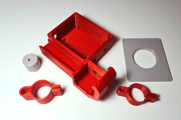
I designed all the parts in Fusion 360, sliced them in Cura and printed them with my Ender 3 V2 in PETG at 0.2mm layer height. You will need to print:
- The “Base.stl“
- The “RotatorDispenser.stl“
- The “CoverBase.stl“
- The “LaserClamp.stl“
- And the “LdrClamp.stl“
You can find all the files Here
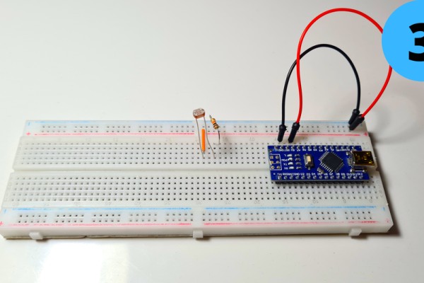
Step 3: Circuit Part 1
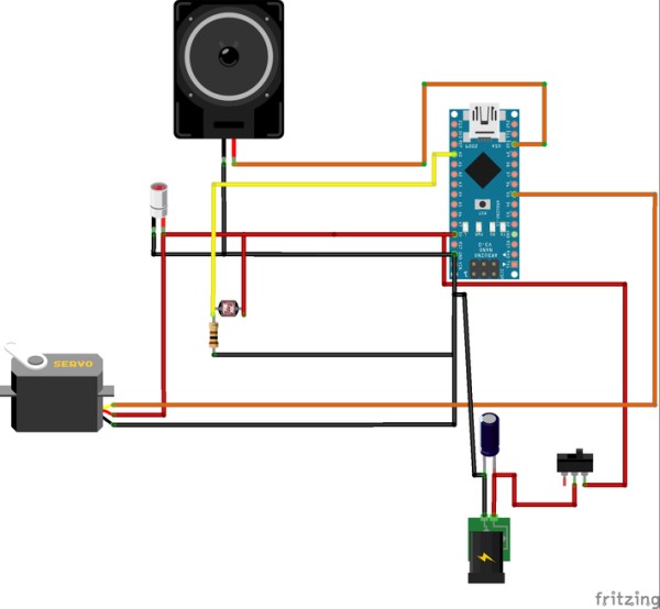
It’s time to connect the electronics!!
1. Place the Arduino Nano on the breadboard
2. Connect 5V to Positive Rail (red) and GND to Negative Rail (blue)
Step 4: Circuit Part 2
3. Add the LDR and connect one of its leads to 5V and the other one to GND with the 1kΩ resistor (the order doesn’t matter)
4.Connect the second lead to A0 as well
5.Add the MG90S Servo and connect its Brown Wire to GND and its Red Wire to 5V
Step 5: Circuit Part 3
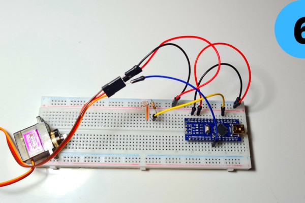
Connect the YellowWire to D5
7. Add the small speaker and connect its Red Wire (+) to D11 and its Black Wire (-) to GND
8. Finally add the Laser Module and connect its Red Wire (+) to 5V and its Black Wire (-) to GND
Step 6: Programming
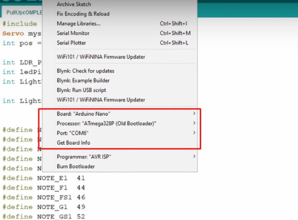
Time to program the Arduino Nano! I have attached my code below for you to download if you want. Open Arduino IDE select the Arduino Nano Board, your COM Port, click Upload and you’re done! The LightThreshold defines how sensitive the LDR is to light, keep this in mind as I’ll go into it deeper in the next step.
Take a look at adithyalokesh17‘s work as well! He has turned a lot of popular songs (Like “Take on me” which I used) into light Arduino code which is easy to use with buzzers and speakers without needing any complicated SD card readers etc.
Step 7: Test/Troubleshooting
When the code gets uploaded nothing happens. Then I cover the LDR with my finger so that I block the light from reaching it. Pretty much a simulation of what will happen during the workout when my hands will block the laser beam. In both cases the If statement gets triggered, music starts playing and then the servo rotates and dispenses a Tic Tac.
There are two common problems that can ocure here even if you did everything properly.
- The music doesn’t start playing when you cover the sensor. You can easily solve this by increasing the “LightThreshold” value we talked in the previous step thus making it more sensitive.
- The music starts playing without even covering the sensor. You can solve this be decreasing the “LightThreshold” value thus making it less sensitive.
Tips:
- A good tip to adjust the Threshold value just right would be to use the serial monitor and see the light values your sensor produces. (The can range anywhere between 0 (Absolute Darkness) to 1023 (Absolute Light)
- To get accurate measurements I would suggest aiming the laser diode to the LDR and working with those values instead of the ones of the ambient light of your room.
Step 8: Circuit Board
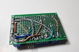
Since everything works it’s time to make a pcb to fit all the components in a more compact enclosure. The only difference the PCB has from the breadboard circuit we made earlier is that I’ve included a Power Input terminal which connects (+) to 5V and (-) to GND and I have added a 100μF capacitor (optional) in parallel to smooth out the current.
Source: Smart Pull-Up Bar
- What triggers the Smart Pull-Up Bar to play music?
The laser beam being blocked by your hands causes the LDR reading to drop, triggering the Arduino to play music. - How is a Tic Tac dispensed?
An MG90S servo rotates a 3D printed rotator dispenser to release a Tic Tac when the sensor remains blocked after the song. - What components are needed to build the laser sensor?
A laser diode aligned to an LDR with a 1kΩ resistor (and connections to 5V, GND, and analog input A0) form the sensor. - Can I adjust sensor sensitivity if it misbehaves?
Yes, change the LightThreshold value in the Arduino code; increase to make it more sensitive, decrease to make it less sensitive. - How can I get accurate light measurements to set the threshold?
Use the Arduino serial monitor to read the LDR values while aiming the laser directly at the LDR for accurate measurements. - Is a PCB necessary for the project?
No, a breadboard works for testing; a PCB is optional for a more compact enclosure and adds a power input terminal and optional 100μF capacitor. - Which Arduino pin controls the speaker and servo?
The speaker is connected to D11 and the servo signal wire is connected to D5 in the described build. - What 3D printed parts are required?
Print Base.stl, RotatorDispenser.stl, CoverBase.stl, LaserClamp.stl, and LdrClamp.stl as provided by the author.