Summary of Tilt Compensated Compass
This project details building a tilt-compensated compass using an Arduino Uno R3, an LCD display, and an MPU-9250 sensor module combining an MPU-6050 accelerometer/gyro and AK8963 magnetometer. The compass calculates accurate heading, pitch, and roll, correcting for tilt to maintain heading accuracy within 2 degrees. It includes calibration procedures to counter hard-iron and soft-iron distortions. The compass can disable tilt compensation via a jumper and requires modification of the Arduino I2C Wire library. The project costs around $20 and is unsuitable for critical navigation due to gyro limitations under rapid movement.
Parts used in the Tilt Compensated Compass:
- Arduino UNO R3 and USB cable
- Serial LCD display
- MPU-9250 accelerometer/gyro/magnetometer sensor module
- Arduino female-to-female jumper cables (2 pieces)
- Arduino male-to-female jumper cables (6 pieces)
- 9 volt battery
- 9 volt battery clip/leads
- Scrap plastic sheet for base
- Threaded nylon spacers (12 pieces)
- M3 x 5mm bolts (20 pieces)
This instructable explains how to make a tilt compensated compass using an Arduino UNO R3, an LCD display, and an IvenSense MPU-9250 multi-chip-module that contains an MPU-6050 accelerometer / gyro and an AK8963 magnetometer within the same package.
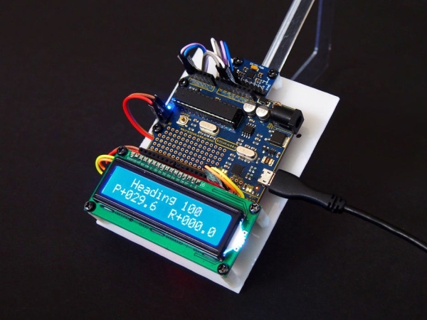
The LCD simultaneously displays the Heading, (P)itch, and (R)oll.
The heading accuracy is within 2 degrees depending on how well the compass has been calibrated.
Without tilt compensation the compass headings vary significantly … sometimes by as much as 100 degrees.
When stabilised, the tilted compass headings only vary by one or two degrees … the improvement is amazing.
The tilt stabilization may be disabled by placing a jumper wire between Arduino pins A0 and GND.
The estimated cost for this project is $20 USD.
Images
The opening photo shows the tilt compensated compass resting on a 30-60 degree set square. The pitch angle is approximately 30 degrees, the roll angle is zero, and the heading is 100 degrees magnetic.
The video shows the compass both “with” and “without” tilt compensation.
Warning
Do not use this compass in situations involving safety to life, such as navigation at sea, as violent shaking (rapid movement) can affect the gyro accuracy requiring a system reset.
Step 1: Circuit Diagram
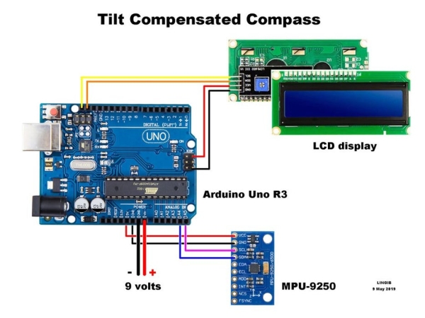
Photo 1 shows how the Arduino UNO R3, the LCD display, and the MPU-9250 accelerometer/gyro/magnetometer are wired together.
The tilt stabilization may be disabled by placing a jumper wire between Arduino pins A0 and GND.
The MPU-9250 must:
- be flat when the compass is placed on a level surface.
- be clear of any ferrous metals.
Step 2: Parts List
The following parts where obtained from https://www.aliexpress.com/
- 1 only Arduino UNO R3 and USB cable
- 1 only serial LCD display
- 1 only MPU-9250 accelerometer/gyro/magnetometer
- 2 only Arduino female-to-female jumper cables
- 6 only Arduino male-to-female jumper cables
The following parts were obtained locally:
- 9 volt battery
- 9 volt battery clip/leads
- Scrap plastic sheet for base
- 12 only threaded nylon spacers
- 20 only M3 x 5mm bolts
The estimated cost for this project is $20 USD.
Step 3: Theory
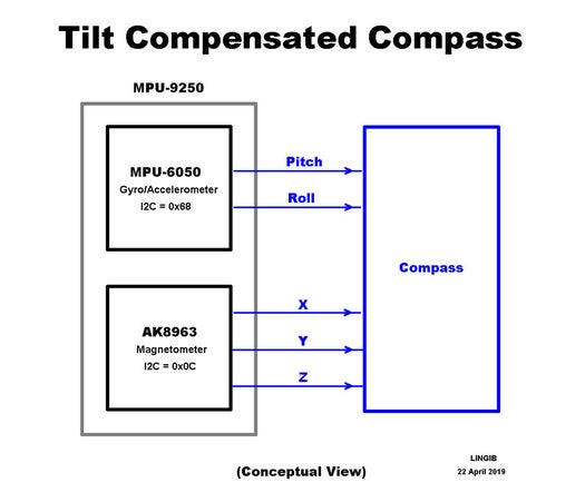
Tilt compensated compass
A conceptual view of a “tilt compensated compass” is shown in photo 1.
The InvenSense MPU-9250 chip contains two separate integrated circuits within the same package:
- an MPU-6050 gyro / accelerometer and
- an AK8963 magnetometer from Asahi/Kasei
Calculating pitch and roll
Assume that:
- We are in an aircraft that is heading north (up the page) along the gyro X axis.
- The Z (yaw) axis is pointing down, and
- the X (pitch) and Y (roll) axes are both horizontal
- The pitch and roll readings are both zero
Let’s now raise the aircraft nose by 45 degrees:
- The roll reading remains at zero since there is no rotation about the roll axis.
- The pitch reading becomes 45 degrees due to the rotation about the pitch axis.
- The yaw axis is now tilted by 45 degrees.
Let’s now yaw the aircraft by 90 degrees:
- The Yaw axis remains tilted .
- The pitch should now read zero as the aircraft body is now horizontal.
- The roll should now read 45 degrees as the wings are now tilted.
Since there was no rotation about either the pitch or roll axes, the pitch angle still reads 45 degrees, and the roll angle is still reads zero … we have a problem!
Enter the accelerometer which is able to measure acceleration about each of the XYZ axes. As the aircraft yaws the accelerometer allows us to gradually transfer the pitch reading to the roll reading, and vice versa.
The Accelerometer is also able to correct for gyro drift … our pitch and roll readings are now correct!!
The following two Youtube videos explain how this is done:
Determining the compass heading
The X and Y outputs from the AK8963 magnetometer allow us to determine the compass “heading” using the formula:
- Heading = atan2(Y, X) * RAD_TO_DEG;………………………………………………………………….. (1)
This “heading” is only valid while the compass is level … any tilt and the reading will change dramatically. This variation can be greater than 100 degrees !!!!
The solution is to fool the compass into thinking that it is always horizontal.
We do this by plugging the “pitch” and “roll” values from the MPU-6050 into equations (2) and (3) and using these new (compensated) values in equation (1):
- Xhorizontal = X*cos(pitch) + Y*sin(roll)*sin(pitch) – Z*cos(roll)*sin(pitch) ……………………….(2)
- Yhorizontal = Y*cos(roll) + Z*sin(roll) ………………………………………………………………………. (3)
The above formulas are found in several of the reference papers below.
When applying these formulas, the orientation of the MPU-6050 and AK8963 XYZ axes within the MPU-9250 package must be taken into consideration.
From the magnetometers point of view:
- X equates to the gyro Y
- Y equates to the gyro X
- and, since the Z axes point in opposite directions, the pitch is negative.
This is fixed by preceding the above equations with the following code:
- Mag_pitch = -Gyro_roll_output * DEG_TO_RAD; ……………………………………………………… (4)
- Mag_roll = Gyro_pitch_output * DEG_TO_RAD; ………………………………………………………. (5)
Theoretically, any variations in the compass heading due to tilt will disappear. In practice there is still a small variation of one or two degrees as shown in photo 2.
Inspiration
The “pitch” and “roll” code for this compass is modeled on the MPU-6050 IMU (Inertial Management Unit) described by Joop Brokking, http://www.brokking.net/imu.html.
The algorithm for calibrating the magnetometer is described in the following article by Kris Winer, https://github.com/kriswiner/MPU6050/wiki/Simple-a…
The remaining code is my own.
References
- “MPU-9250 Product Specification Revision 1.1”, IvenSense, https://www.invensense.com/wp-content/uploads/201…
- “MPU-9250 Register Map and Decriptions Revision 1.6”, IvenSense, https://www.invensense.com/wp-content/uploads/201…
- MPU-6050 IMU (Inertial Management Unit), by Joop Brokking, http://www.brokking.net/imu.html
- “Simple and Effective Magnetometer Calibration”, Kris Winer, https://github.com/kriswiner/MPU6050/wiki/Simple-…
- “Applications of Magnetic Sensors for Low Cost Compass Systems”, Michael J. Caruso, Honeywell, SSEC http://www.brokking.net/YMFC-32/YMFC-32_document_…
- “Applications of Magnetoresistive Sensors in Navigation Systems”, Michael J. Caruso, Honeywell Inc., https://aerospace.honeywell.com/en/~/media/aerosp…
Step 4: Software Installation
It is essential that you perform this step BEFORE uploading the compass code to your Arduino
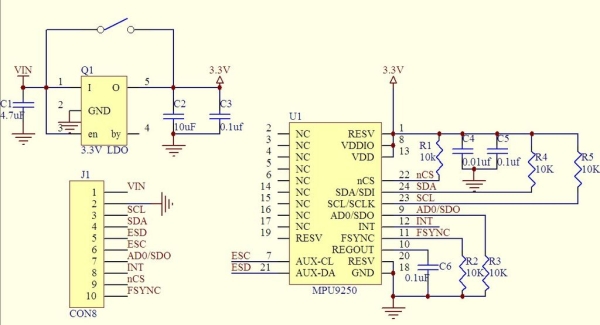
Editing your I2C Wire Library.
According to the breakout board schematic (photo 1), the MPU-9250 chip has 10K ohm pull-up resistors connected to 3.3 volts on each of the SDA (data) and SCL (clock) lines.
The Arduino, however, has internal pull-up resistors to 5 volts. These pull-up resistors are not required and should be disabled to prevent the I2C lines from rising above 3.3 volts and damaging the MPU-9250.
I recommend editing lines 75 ,76, & 77 in file “C:Users\…\Documents\Arduino\libraries\Wire\utility\twi.c” to read:
- // deactivate internal pullups for twi.
- digitalWrite(SDA, 0);
- digitalWrite(SCL, 0);
These commands could be placed inside the Arduino setup() function following the Wire.begin() function but it is still possible for the I2C lines to rise above their safe voltage level until the code lines are run.
Use a text editor such as Notepad++ when editing any files. Do NOT use a word processor.
Installing the compass code
- Disconnect the I2C lines from your Arduino [1]
- Edit your I2C Wire library as described above.
- Copy the contents of the attached “”tilt_comp_compass.ino”” file into an Arduino sketch.
- Save the Arduino sketch as “”tilt_comp_compass” (without the quotes).
- Compile and upload the sketch to your Arduino.
- Unplug the Arduino.
- Connect the Arduino I2C lines.
- Apply power to your project.
Notes
[1]
The reason for disconnecting the I2C SDA (data), and SCL ( lines is that Arduino pins A4 & A5 may be in an output “high” state from a previous project. Disconnecting these wires eliminates the possibility of 5 volts damaging the MPU-9250.
[2]
16 September 2019
The code “tilt_comp_compass_v1.01.ino” contains a minor bug-fix.
Step 5: Calibrating
Depending on their orientation with respect to the Earth’s magnetic field, the XYZ outputs from the magnetometer change from +ve to -ve (positive to negative) as the magnetometer is rotated.
If you rotate the MPU-9250 about each axis, the XYZ outputs should each plot a perfect circle centered about the 3D XYZ coordinate (0,0,0).
Hard-iron distortion
In practice these circles are NOT centered over the 3D coordinate (0,0,0) but are displaced either up or down, or to the left or right.
These displacements are due to “Hard-iron” distortion from, say, a magnetised object such as a speaker. Such distortions are always additive and the offsets can be calculated (then subtracted) using the following code: [1]
- Mag_x_offset = (mag_x_max + mag_x_min) / 2;
- Mag_y_offset = (mag_y_max + mag_y_min) / 2;
- Mag_z_offset = (mag_z_max + mag_z_min) / 2;
Soft-iron distortion
There is also another form of distortion called “Soft-iron” distortion” that arises from the proximity of ferrous, and other materials, that disturb the earth’s magnetic field.
The effect of “soft-iron” distortion is to turn the ideal circles into ellipses which has the effect of altering the compass heading.
The solution to this problem is to scale the X and Y readings in such a way as to form perfect circles. This is achieved using the following code: [1]
- chord_x = ((float)(mag_x_max – mag_x_min)) / 2;
- chord_y = ((float)(mag_y_max – mag_y_min)) / 2;
- chord_z = ((float)(mag_z_max – mag_z_min)) / 2;
- chord_average = (chord_x + chord_y + chord_z) / 3;
- Mag_x_scale = chord_average / chord_x;
- Mag_y_scale = chord_average / chord_y;
- Mag_z_scale = chord_average / chord_z;
The “calibrate_magnetometer()” function does this for you and MUST be run before you can use the compass. Theoretically this function is not required again unless you change your location.
Instructions for doing this are given in the “tilt_comp_compass.ino” code header.
Simply change the line “bool Record_data = false;” to read “bool Record_data = true;”, upload “tilt_comp_compass.ino” to your Arduino, then tumble the compass in all directions until a set of data values appear on your screen. This process will take about one minute.
Copy the screen values into the matching header positions, set “bool Record_data = false;”, upload “tilt_comp_compass.ino” once more and you are ready to go.
Calibrating the gyro
The gyro calibration is automatic and MUST be done each time you power-up the compass. [2]
Place the compass on a level surface and apply power … a progress bar will appear on the LCD display after which the compass display will appear.
The compass display shows the:
- Heading
- Pitch
- Roll
The pitch and roll headings should both indicate 000.0 +/- 0.1 when the calibration process is complete. If not then edit the following code lines in the main loop() until the residual pitch and roll readings are zero:
- Accel_pitch -= -0.2f;
- Accel_roll -= 1.1f;
True (Geographic) North
By default the compass indicates Magnetic North.
The heading can be changed to True North by uncommenting the following code line that appears in the main loop():
- // Heading += Declination;
You will also have to replace the “Declination” value in the Arduino “header” with that of your own location.
References
[1]
“Simple and Effective Magnetometer Calibration”, Kris Winer, https://github.com/kriswiner/MPU6050/wiki/Simple-…
[2]
The gyro calibration assumes that a yaw angle of exactly 360 degrees is obtained when the MPU-9250 is rotated one full revolution.
Assuming that the crystal (xtal) frequency in your Arduino UNO is exactly 16 MHz, then a main loop() time of 8000 us (microseconds) is required. Unfortunately my Arduino crystal frequency is off by about 5%. For this reason I have set my loop time to 8400 uS.
Instructions for adjusting your gyro sample (loop) time are found at the end of the main “loop() function.
The following (temporary) code will display the yaw reading on your Serial Monitor:
- Serial.println(Mag_z);
Step 6: Summary
The tilt compensated compass:
- Uses a single MPU-9250 chip that contains two integrated circuits within the same package.
- The tilt and roll is determined by the internal MPU-6050 gyro / accelerometer chip.
- The internal AK8963 magnetometer chip provides X,Y outputs from which the compass heading may be calculated.
- The compass heading is only accurate if the magnetometer X,Y outputs are taken when the compass is level.
- The pitch and roll values from the MPU-6050 gyro / accelerometer are used to cancel the variations in the magnetometer X,Y outputs due to tilt.
- Once calibrated the resulting compass headings are accurate to within 2 degrees.
- Tilt compensation can be disabled using a jumper between Arduino pin A0 and GND.
- The Arduino I2C pull-up resistors should be disabled in the “Wire” library.
- The Compass wiring should be connected after the “tilt_comp_compass.ino” code has been uploaded.
- Violent shaking (rapid movement) can affect the gyro accuracy requiring a system reset.
- Accordingly, do not use this compass in situations involving safety to life, such as navigation at sea.
Source: Tilt Compensated Compass