Monitor lightning activity and get alerted on dangerous situations.
Things used in this project
Story
Introduction
Lightning is a phenomenon that always attracted man’s interest. Reasons behind this are the danger as a consequence of a lightning stroke on the negative side and the visual part which many people find it beautiful on the positive side. Regarding the first part (i.e. the danger), sensing a lightning event from a distance and taking precautionary measurements can prevent damage in electrical equipment and most importantly prevent serious injuries or death. These effects are even more important when living in the countryside and working in the open fields (e.g. farmers, scheduling sports and leisure activities, workers in constructions and maintenance operations like wind and solar parks etc.)
The necessity for realizing a low-cost distributed network for lightning activity sensing has lead us to design and implement such an IoT lightning sensing network using an Arduino MKR1000 and an AS3935 Lightning Sensor, named the Thundercatch sensor. The Thundercatch sensor node realized collects and uploads lightning activity data to the cloud using the Microsoft Azure platform for storage and analysis. For demonstrating the capabilities of recording and processing, we have developed a web site for visualizing data in combination with geospatial information using freely available GIS services. The main advantages of such a sensing network is the minimum cost for the sensing nodes based on a low-cost WiFi connected ARDUINO IoT solution, the simple software architecture introduced and the obvious scalability and high performance cloud interconnectivity provided. The Thundercatch platform can be adopted as a paradigm for enabling any IoT based sensing and actuation solution and therefore contributes to the IoT ARDUINO community with a simple and high value solution.
Lightning Strikes and Sensor Operation
When lightning strikes it emits an electro-magnetic pulse (EMP) which extends in a wide frequency band. For lightning detection three frequency bands are used according to the literature:
1) Around 7.5Hz (Schumann resonances)
2) Around 300kHz and
3) Around 30MHz
Going upwards towards higher frequencies, the distance that the sensor can detect the lightning activity reduces, since higher electromagnetic frequencies are expected to be strongly attenuated when propagating in free space.
The AS3935 is a lightning sensor in an integrated circuit. It can distinguish between man-made electro-magnetic waves and real lightning. It connects with a MCU with SPI or I2C serial interfaces. In this project, a breakout board was used from MikroElectronika named Thunder click.
The sensor uses a LC circuit with resonance frequency at 500kHz. This frequency is close to the 300kHz area and is used probably because it is a relatively quiet frequency (used for amateur radio or international calling and distress). When a lightning strikes, the LC circuit tunes with the electromagnetic wave from lightning. Special algorithms are utilized for rejecting false alarms generated from manmade activity. When the sensor detects a wave at said frequency, it raises an interrupt to the connected MCU which reads the sensor registers and publishes the acquired measurements to the cloud with the appropriate software.
The Lightning Sensors Network
Although this project is a specific use case for the Arduino, the Lightning Sensor and Microsoft Azure, the ultimate goal is to contribute towards the formulation of a network of said such devices spread around the world providing useful data for lightning events in the globe. In this way, a community will be formed consisting of users having only the consumer role (getting lightning activity information for the region of their interest) or the contributor role as well (by feeding data from the Thundercatch sensor to the cloud platform). As a consequence of the scalability of the proposed cloud infrastructure, the granularity and accuracy of the results will be linear dependent to the number and distribution of the contributing sensing nodes; as the number and the area covered escalates in a geographical region, higher accuracy will be achieved with the results provided. Users may get benefit from this community in multiple ways, e.g. a mobile application can alert them for lightning activity nearby or to any other depending of their location, or the Thundercatch platform could act as a centralized source of data for existing weather web sites that will consolidate lightning activity with other weather parameters and increase the value of the presented information to the their users. For demonstration purposes a web site is located at thundercatch.azurewebsites.net for data visualization.
Hardware and Software requirements
The Thundercatch platform has followed a simple hardware and software approach targeting to demonstrating the IoT capabilities of the Arduino MKR1000 platform for realizing a sensing network. Specifically for hardware you will need
1) An Arduino MKR1000
2) A Thunder click
3) Female/Female Jumper Cables
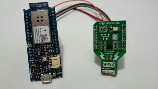
As far as software is concerned, an active subscription to Microsoft Azure and Microsoft Visual Studio 2015 is needed (with a free subscription offered from Microsoft for testing).
Arduino Interface with the Thunder Click
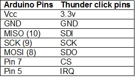
Thunder click uses SPI for communicating with the Arduino. So we need four wires for the SPI. Also, there is the interrupt signal and lastly power and GND connections. The interconnection table between the two boards is following.
Azure Services Set Up
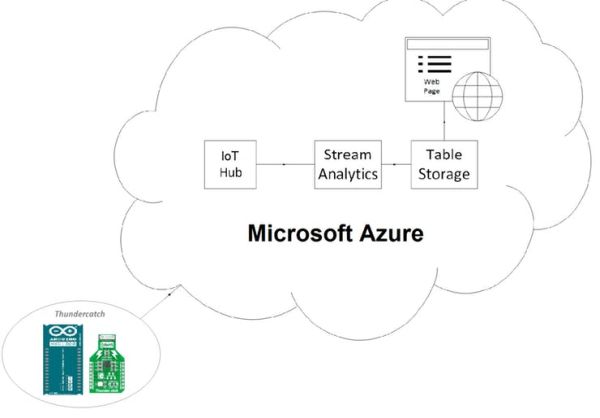
For minimum cloud connectivity we will need at least three services from Microsoft Azure.
1) Azure IoTHub
2) Azure Stream Analytics
3) Azure Table Storage
4) Azure Web App
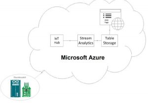
IoTHub is used for sending data from the sensor. Stream Analytics listens for data and saves them to Table Storage. In the Web App a web site is developed for viewing the data.
1) Setting up Azure IoTHub
Go to https://portal.azure.com and create a new Azure IoT Hub (it is under Internet of Things). Enter your desired name and click Create. After creation, select it and go to Settings. Click on Shared Access Policies and then on iothubowner. Write down the Connection String and the Primary Key (you will need these later).
2) Create Table Storage
Go to New ->Data + Storage-> Storage account to create a Storage account. Leave Resource Manager as deployment model. Name it whatever you like and click Create. When it finishes go to Settings -> Keys and write down the Primary Access Key.
3) Creating and Configuring Stream Analytics
Stream analytics Service helps in Listening to Event Hub data, processing them and then writing them to a storage.
Again under Internet of Things select Stream Analytics Job. Give it a name and wait to finish creating. When it is done, select the newly created job and select Inputs. Click to add a New Input. Give input a name. In Source Type select Data stream. Source is IoT hub. Next, write the name of the IoT hub you created earlier, on Shared access policy name enter iothubowner and on key the Primary Key you wrote down when you created IoT hub.
Next go to Query and add the following:
SELECT
*
FROM
[input name you created earlier]
Lastly go to Output and add a New Output.
As a sink select Table Storage. On the next screen enter and alias for the output. On the Storage account and Storage account key fields enter the information you wrote down from Storage account creation. On table name you can enter anything you like (table will be created automatically). Also on Partition Key and Row Key you are free to name them as you like (write down those names because you are going to need them later).
4) Creating the Web App
Web+Mobile-> Web App
Enter the URL and click Create. On Settings -> Deployment Source you can choose how to deploy the source code.
Arduino Code
Arduino is connected to your Wi-Fi network. When an event occurs, it reads data from the sensor and then connects to the Event Hub where it sends the data. Before uploading the sketch to the Arduino, you have to enter some information.
Before configuring Arduino code, download Device Explorer. https://github.com/Azure/azure-iot-sdks/releases/download/2016-03-11/SetupDeviceExplorer.msi Follow the instruction on https://github.com/Azure/azure-iot-sdks/blob/master/tools/DeviceExplorer/doc/how_to_use_device_explorer.md to create a device for your IoT Hub and a SAS token.
First of all, in the Arduino code, you have to enter you Access Point name and password. This is needed to connect Arduino to your local Wi-Fi network. On iotHubURL, you want to enter the IoT Hub URL. On path you replace [Device Name] with a name you want for your device. Lastly, in order to write to the Event Hub you need the authorization token you created with Device Explorer. Just copy the part starting from “SharedAccessSignaturesr=” and paste it on SAS.
Now you are ready to start sending data to the cloud.
A Bit About the Code…
When Arduino boots, it tries to connect to a Wi-Fi network. If it can’t connect after some retries, it gives up and continues. If it connects to network it gets the current epoch time. This will act as seed to the random number generator. Random number generator is needed as a Row Key for the table (it has to be unique). After that it initializes the sensor and goes to main loop. When an interrupt occurs Arduino reads the cause from the sensor (and the distance if it was a lightning) and prints it to the serial console. If a connection to the Access Point was made earlier, it sends an HTTP POST request to Azure IoT Hub. Finally, it returns back to main loop. There is an option to temporary change sensor parameters (until next restart). This is done by serial console. Sending a question mark (with a line ending) in Arduino returns the help menu with the possible options.
Configuring Web Site
Before deploying the web site, you have to change two parameters in Map.aspx.cs and RawData.aspx.cs. There you will write the Table Storage credentials. That is the Table Storage name and Access Key. After that you can deploy the website with any method you chose.
Code
Source : Thundercatch IoT Network

