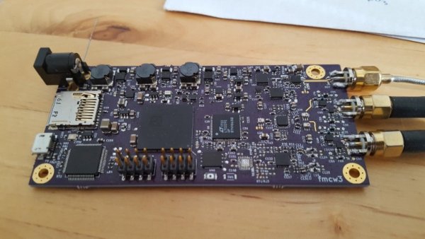
Introduction
Previously I made a simple frequency-modulated continuous-wave (FMCW) radar that was able to detect distance of a human sized object to 100 m. It worked, but as it was made with minimal budget and there was a lot of room for improvement.

FMCW radar working principle
If you have read my previous articles you should know how FMCW radar works, but for completeness sake short explanation is given below:
Frequency Modulated Continuous Wave (FMCW) radar works by transmitting a chirp which frequency changes linearly with time. This chirp is then radiated with the antenna, reflected from the target and is received by the receiving antenna. On the reception side the received signal that was delayed and undelayed copy of the transmitted chirp are mixed (multiplied) together. The output of the mixer are two sine waves that have frequencies of sum and difference of the waveforms. The frequencies of the received signals are almost the same and the sum waveform has frequency of about two times of the original signal and is filtered out, but the difference waveform has frequency in kHz to few MHz range. The difference frequency is dependent on the delay of the received reflection signal making it possible to determine the delay of the reflected signal. The electromagnetic waves travel at speed of light which allows converting the delay to distance accurately. When there are several targets the output signal is sum of different frequencies and the distances to the targets can be recovered efficiently with Fourier transform.
Issues with the previous version
The biggest issue with the previous version was noisy power supplies causing spurs in the received signal, ADC sampling clock not being locked to PLL reference clock and microcontroller being too slow.
To save money I had chosen to use two buck converters to power all the digital and analog components. Even though I chose the switching frequency of the converters to be above the IF frequency, there ended up being some spurs also at lower frequencies. Adding capacitance and swapping the inductors for better shielded ones helped the problem but didn’t completely solve it. The proper fix is to add linear regulator after the buck converters to clean up the switching noise.
The problem with separate clocks for ADC and PLL caused the sampling interval of the ADC to vary between separate sweeps. The maximum offset was only +- half a sample and it wasn’t a big issue when only doing range measurements. However when trying to measure heartbeat and respiratory rate the added phase noise from the varying sampling interval caused some noise in the measurements. Noisy power supplies also degraded the phase noise performance. The fix for this one is pretty easy: Use the same clock for both ADC and PLL.
The microcontroller I was using was pretty powerful compared to the cheapest 8-bit microcontrollers, but it was hopelessly underpowered to do any kind of digital signal processing. All of processing power and internal memory was spent in getting the samples from ADC to PC through USB fast enough. Sampling speed of the ADC was 10 MHz and because of lack of DSP resources every sample needed to be transferred to PC. Even the samples between the sweeps that didn’t have any useful data were transferred to PC only to be discarded later. With more resources it would have been possible to do digital filtering, lower the sampling speed and only transfer the useful samples.
Microcontrollers don’t really have enough processing power to do any kind of non-trivial filtering. For example a 100 tap FIR filter requires 100 multiplications and 100 additions for every sample. Even if the multiplication could be done in one clock cycle the maximum sample rate is too low to be useful. The microcontroller should also have enough processing power to transfer ADC samples and do communication and other logic. FPGA works much better for DSP as the operations can be done in parallel.
Read more: Third version Homemade 6 GHz FMCW radar
