
Summary of Theremin Toy using Arduino
This article details the creation of "Oh," a Theremin-inspired toy for children that generates sound and changes RGB LED colors based on distance detected by an ultrasonic sensor. The project combines existing code for audio and lighting, integrated into a compact case using an Anarduino kit and an ATMEGA328P chip. Special wiring techniques are used to merge sensor signals and control current to the LED.
Parts used in the Oh Theremin Toy:
- Ultrasonic Module HC-SR04
- Anarduino An Arduino Compatible 24 DIP model kit
- BreadBoard with Power Supply
- Mini Speaker Item G19651
- Module Wiring Dupont Wire Connector Cables 20cm
- RGB LED Common Anode 5MM LED
- LED Holder 5MM
- 2.1mm DC Pwr Jack
- 3/8 inch bolts for mounting speaker
- 1K Ohm Resistor 1/8W or 1/4W
- Molex Header Item G18974
- Heat Shrink Tubing
- Case enclosure MB-132
- Arduino UNO
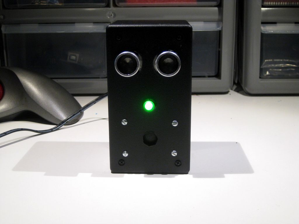
I wanted to make a little toy for my granddaughter to play with when she visits. I know like most kids, she enjoys things that make sounds and have different colored lights on them and if she does something, the toy does something. I thought about a Theremin and decided to add a RGB light that changes color in a similar way that the sound does. This gave “birth” to “Oh”.
I call it “Oh” because when I look at it, it sort of reminds me of a face saying the letter “O”. Try it yourself. Look in a mirror and say “Oh”. There you have it.
Nothing earth shattering here. I “borrowed” some code that was already out there for the Theremin and for playing with RGB LEDs, tweaked them a bit and put it all altogether in one of my little cases.
Here’s a video of it in action.
Step 1: Parts
Ultrasonic Module HC-SR04@ $2.50 on eBay
Anarduino An Arduino Compatible 24 DIP model kit @$5.40 on eBay
BreadBoard P.S. Breadboard Power Supply @$1.50 on eBay
Mini Speaker Item G19651 at Electronic Goldmine @$1.25
Module Wiring Dupont Wire Connector Cables 20cm (female-female) @$1.50 on eBay
RGB LED Common Anode 5MM LED 50 for $4.00 on eBay LED Holder
5MM LED holder 50 for $1.39 on eBay
2.1mm DC Pwr Jack @ 50 Cents
#2 hardware I use 3/8 inch bolts to mount speaker on case. Check out jameco.com
1K Ohm Resistor 1/8W or 1/4W to control current to RGB LED
Molex Header Item G18974 at Electronic Goldmine @$2.00 / 10
Heat Shrink Tubing @$5.00 for an assortment of sizes and colors on eBay
Case enclosure MB-132 at allelectronics.com @$3.00
Arduino UNO Used to program ATMEGA328P chip
Step 2: Wiring it up and putting it together
First, grab the code from the next step and program the ATMEGA328P chip in your UNO and then set that aside.
Next, we will work on the Anarduino.
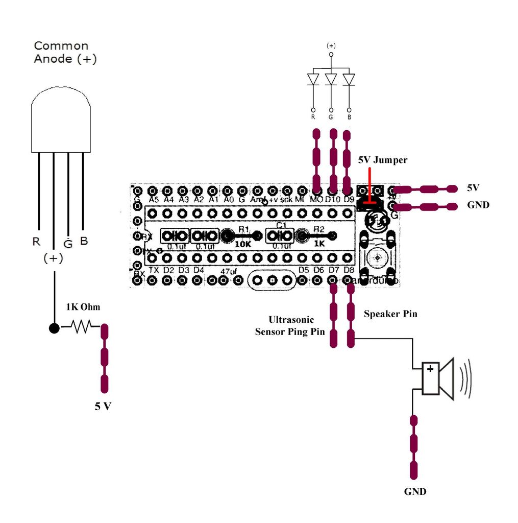
The first picture above shows the wiring of the Anarduino after it is made and the Molex pins are added. See my Kitchen Sink Clock Instructable for more info on putting the Anarduino kit together.
To fix up the Bread Board P.S. for use in this project please see the video in my Instructable about that.
Some special wiring is done in this project to make a “Y” cable to tie the Trig and Echo pins together on the Ultrasonic Sensor into one “signal” line. You can see what I mean by looking at the long orange lead on the right hand side of the second picture. I have a piece of orange heat shrink tubing covering the exposed solder connection.
There is one other special wiring and that is a bit harder to see. The purple wire going into the RGB LED connects to a 1K ohm resistor and the other end is soldered to the anode lead of the LED. I have that covered with purple heat shrink and, if you zoom in on that section of the photo, you might be able to see the “bump” in the line which is the resistor.
Other than those two things everything is pretty straight forward.
Plug the programmed ATMEGA328P chip into the Anaduino socket and you are all set to put it all together.
Looking at the second picture, you can see how I laid out everything and then secured things down with double sided foam tape.
At this point it is a simple thing to plug in all the connectors to the right pins on the Anarduino and the power supply module as per the wiring diagram above in the first picture.
Please test it out before you screw down the cover to make sure you have all your connections right.
For more detail: Theremin Toy using Arduino
- How is the sound and light generated?
The toy uses an ultrasonic module to detect distance, which triggers sound and changes RGB LED colors similarly to a Theremin. - What chip is used to program the device?
An ATMEGA328P chip is programmed using an Arduino UNO before being inserted into the Anarduino socket. - How are the Trig and Echo pins connected?
A special Y cable ties the Trig and Echo pins together on the Ultrasonic Sensor into one signal line. - How is the RGB LED current controlled?
A 1K ohm resistor is soldered between the purple wire and the anode lead of the RGB LED. - What components are used to secure the parts inside the case?
Double sided foam tape is used to lay out and secure everything down inside the enclosure. - Where can I find information on assembling the Anarduino kit?
The author references a Kitchen Sink Clock Instructable for more info on putting the Anarduino kit together. - Can I test the connections before closing the case?
Yes, you should plug in all connectors and test it out before screwing down the cover to ensure connections are correct. - What hardware is used to mount the speaker?
3/8 inch bolts are used to mount the speaker on the case.
