Who wants grinning faces and candles when you can have an interactive pumpkin this Halloween? Play your favorite block-stacking game on an 8×16 grid carved into the face of the gourd, lit by LEDs and using the stem as a controller.

This is a moderately advanced project and requires experience soldering and programming in the Arduino environment. You’ll be working with organic matter and all its inherent quirks, so measurements may need to be adapted to fit the pumpkin you’re using.
Step 1: Required Materials
To build your own Pumpktris you’ll need the following:
Components
- 128 5mm amber LEDs (I used these from Mouser)
Buy some extra to cover any mistakes or tests. I got 140. Amber most closely resembles the flame that would be inside a traditional jack-o-lantern, but you’re free to use any color you like. - Arduino microcontroller
- 1/16″ Heat shrink tubing (11 feet, or 256 1/2″ long pieces)
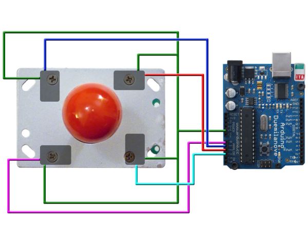
- Arcade joystick with a removable handle (this one from SparkFun worked well for me)
- 4 #6 nylon drywall anchors
This isn’t the kind with the toggles, but the kind that look like screws with deep threads - 4 half-inch long screws of the same size and type that came with the drywall anchors.
The ones that come with the anchors will be too long. - 6mm x 50mm bolt (or whatever size matches the mount for your joystick handle)
- 6mm coupling nut (or whatever size is needed to match the above bolt)
A coupling nut looks like a regular nut, but is about an inch long and is used to join two bolts or pieces of threaded rod.
And last but not least, you’ll need 1 pumpkin. You only need one, but I recommend two so that you’ve got one you can use to practice drilling and cutting. Your LED matrix is going to cover an area approximately 4″ wide by 8″ tall, so you want a pumpkin with an area that size as smooth and flat as possible so your matrix doesn’t wrap too far around. You could use a foam pumpkin, but where’s the magic in that? I can’t speak to the carving techniques needed on a foam pumpkin.
Tools and Consumables
- Soldering iron
- Solder
- Wire cutters
- Wire strippers
- Power drill
- Hacksaw
- X-Acto knife
- 13/64″ drill bit
- 1-1/8″ drill bit (I used a Forstner bit, but a spade bit might work too)
- 1/4″ foam core board
Step 2: Building an LED Matrix
Each matrix is made from 64 LEDs and 128 pieces of wire. It’s easiest to cut and strip all of the wires for each matrix ahead of time. Cut 112 into 2.5″ pieces and strip 1/4″ off of each end. Cut the remaining 16 into 12″ pieces and strip both ends. The more consistent you can get your wire lengths, the easier it will be to build and install.
You’ll start by building sixteen eight-segment daisy-chains of wires—each with 7 short and 1 long wire. Twist each end together with the next piece and solder.
To connect the wires to the LEDs you’ll need a jig to hold the LEDS. Draw an 8×8 grid with half-inch spacing on a piece of 1/4″-thick foam-core board, then use an awl to poke a hole slightly smaller in diameter than the LED at each intersection. You’ll have 64 holes when you’re done.
In the top row of holes insert 8 LEDs. The foam-core will stretch to fit the LEDs and will hold them tightly. Align the LEDs so the longer leg—the anode lead— is facing toward you on each. Double-check, because if you get one wrong the matrix won’t work.
Clip each anode lead to about 1/4″ long, and tin it with solder to make it easier to connect the wires.
Cut 8 pieces of heat-shrink tubing into 1/2″ segments. Slide a piece of tubing over the first wire connection, push it back so it’s not affected by the heat of the solder, then solder the wire connection to the LED anode. Slide the tubing down over the connection once it’s cooled. Continue on to the next LED, repeating seven more times the process of sliding on a piece of tubing, soldering the connection, then lowering the tubing over the joint.
When you’ve got a set of eight LEDs all connected to each other, remove them from the jig and repeat again for seven more rows, being sure to make all connections to the anode lead of each LED. You can use whichever row of the jig is easiest to reach, since you’re only working with one at a time.
After all eight rows have been soldered, it’s time to join the columns and make a matrix.
Insert all of the LED strings into the jig you made. Keep the long wire on the same side of each string.
Cut and tin the cathode lead of each LED in the first column, just like you did to build the string. Take another wire chain and repeat the process of soldering it to the LEDs, only this time you’re connecting it at 90 degrees to the first set of wires you did. Keep the long wire on the same side of the matrix.
As you complete each column, remove it from the foam-core jig and fold it out of the way to provide access to the next column.
When you’re all done you’ll have 64 LEDs joined in 8 rows and 8 columns. Unfortunately, you need to repeat the process again for the second matrix. If you need a break, skip to steps 3, 4, and 5 to work on the code, then come back to this.
- 128 5mm amber LEDs (I used these from Mouser)
Buy some extra to cover any mistakes or tests. I got 140. Amber most closely resembles the flame that would be inside a traditional jack-o-lantern, but you’re free to use any color you like. - Arduino microcontroller
- 1/16″ Heat shrink tubing (11 feet, or 256 1/2″ long pieces)
- Arcade joystick with a removable handle (this one from SparkFun worked well for me)
- 4 #6 nylon drywall anchors
This isn’t the kind with the toggles, but the kind that look like screws with deep threads - 4 half-inch long screws of the same size and type that came with the drywall anchors.
The ones that come with the anchors will be too long. - 6mm x 50mm bolt (or whatever size matches the mount for your joystick handle)
- 6mm coupling nut (or whatever size is needed to match the above bolt)
A coupling nut looks like a regular nut, but is about an inch long and is used to join two bolts or pieces of threaded rod.
For more detail: The Tetris Pumpkin using an Arduino