Summary of The Local Weather Station on a Four-Wheels Bluetooth Controlled Car
This article details the construction of a four-wheeled, Bluetooth-controlled robot car equipped with a local weather station. Using a Seeed Wio Terminal and DFRobot Quad DC Motor Driver Shield, the project enables remote movement via Blynk while simultaneously measuring air pressure, temperature, humidity, and light. The system displays real-time data on both the terminal's LCD and the Blynk mobile interface, featuring a custom chassis made from PVC pipes and acrylic.
Parts used in the Four-Wheels Bluetooth Controlled Car:
- Seeed Wio Terminal
- DFRobot Quad DC Motor Driver Shield for Arduino
- Grove - Temperature & Humidity Sensor (DHT11)
- Grove Temperature and Barometer Sensor (BMP280)
- GA25 12V Geared Motor (4 pcs)
- 65mm Rubber Wheel Blue
- GT2 Timing Pulleys 80 Teeth
- Hexagon Motor Coupling For Robot Car Wheel
- Rechargeable Li-ion Battery 18650
- 2 Slot Battery 18650 Holder
- 1 Slot Battery 18650 Holder
- LM2596S 3A Adjustable Step-down DC-DC Power Supply Module
- Arduino Uno Protoshield
- Male & Female Header
- Clear/White Acrylic A4 5mm thickness
- Round On/Off Switch
- 8P/16P Rainbow Ribbon Cable
- Two Core Power Cable
- 5mm DC Male And Female Power Plug
- Cable ties, cable spiral wrap, bolts and nuts
- PVC Pipe Ø42mm
- PVC Pipe Ø60mm
- PVC Pipe Tee Ø42mm
- PVC Pipe End Cap Ø42mm
- PVC Straight Connector Tee Ø60mm
- PVC Pipe End Cap Ø60mm
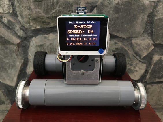
This is my four-wheels bluetooth controlled car which is equipped a local weather station on it. This four wheels car can be fully functional bluetooth controlled via Blynk that allows the car to move forward, backward, turn left, turn right by four DC motors. And it can also measure the weather data on my surrounding such as: air pressure, temperature, humidity, light. It is controlled by Seeed Wio Terminal & DFRobot Quad DC Motor Driver Shield. And all data related to car and weather are shown on both Wio Terminal LCD and Blynk HMI screen.
Please check my introduction video before getting started.
Step 1: Supplies
First of all, I would like to thank the following sponsors who helped me complete this project.
⦾ JLCPCB: for financial support and free PCB sponsor. If you have a PCB project, please visit the JLCPCB website to get exciting discounts and coupons as follows:
- JLCPCB PCB Prototype only $2.
- Get $24 Register Coupon here: jlcpcb.com/cyt
⦾ SEEED STUDIO: support me a Wio Terminal hardware.
⦾ DFROBOT: support me a Quad DC Motor Driver Shield for Arduino.
a. Main materials:
⦾ 1pcs x Seeed Wio Terminal.
⦾ 1pcs x DFRobot Quad DC Motor Driver Shield for Arduino.
⦾ 1pcs x Grove – Temperature & Humidity Sensor (DHT11).
⦾ 1pcs x Grove Temperature and Barometer Sensor (BMP280). I had one Grove Beginner Kit for Arduino which include DHT11 and BMP280 sensor. If you are new to Arduino, you can buy this kit with 10 additional Grove Arduino sensors all in one piece of the board.
⦾ 4pcs x GA25 12V Geared Motor.
⦾ 4pcs x 65mm Rubber Wheel Blue. I only had two of these, so I used GT2 Timing Pulleys 80 Teeth for two remaining wheels.
⦾ 4pcs x Hexagon Motor Coupling For Robot Car Wheel.
⦾ 6pcs x Rechargeable Li-ion Battery 18650.
⦾ 2pcs x 2 Slot Battery 18650 Holder.
⦾ 2pcs x 1 Slot Battery 18650 Holder.
⦾ 1pcs x LM2596S 3A Adjustable Step-down DC-DC Power Supply Module.
⦾ 1pcs x Arduino Uno Protoshield.
⦾ 2pcs x Male & Female Header.
⦾ 1pcs x Clear/White Acrylic, size A4, thickness 5mm.
⦾ 1pcs x Round On/Off Switch.
⦾ 1 meter x 8P/16P Rainbow Ribbon Cable.
⦾ 2 meter x Two Core Power Cable.
⦾ 2pcs x 5mm DC Male And Female Power Plug.
⦾ Cable ties, cable spiral wrap, bolts and nuts.
⦾ 500mm x PVC Pipe Ø42mm & Ø60mm.
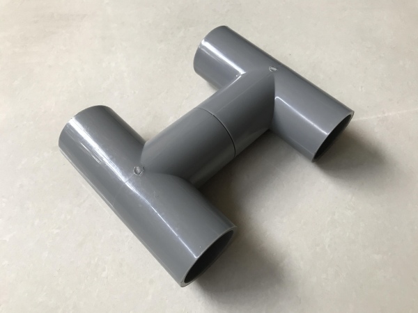
⦾ 2pcs x PVC Pipe Tee Ø42mm.
⦾ 4pcs x PVC Pipe End Cap Ø42mm.
⦾ 1pcs x PVC Straight Connector Tee Ø60mm.
⦾ 2pcs x PVC Pipe End Cap Ø60mm.
b. Tools:
⦾ Drilling machine.
⦾ Hand saw.
⦾ Soldering machine.
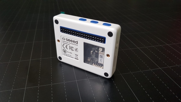
Step 2: Seed Wio Terminal
The Wio Terminal is a SAMD51-based microcontroller with Wireless Connectivity powered by Realtek RTL8720DN that’s compatible with Arduino and MicroPython. It runs at 120MHz (Boost up to 200MHz), 4MB External Flash and 192KB RAM. It supports both Bluetooth and Wi-Fi providing backbone for IoT projects.
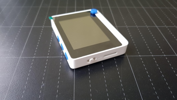
The Wio Terminal itself is equipped with:
- 2.4” LCD Screen.
- Onboard IMU (LIS3DHTR).
- Microphone.
- Buzzer.
- microSD card slot.
- Light sensor.
- Infrared Emitter(IR 940nm).
- 5 Way Switch.
- 3 User Defined Button.
- Built-in RTC functionality inside the SAMD51 core.
- And so on.
On top of that, it also has two multifunctional Grove ports for Grove Ecosystem and 40 Raspberry Pi compatible pin GPIO for more add-ons.
Check detail at: https://www.seeedstudio.com/Wio-Terminal-p-4509.html
Wiki page: https://wiki.seeedstudio.com/Wio-Terminal-Getting-Started/
Step 3: DFRobot Quad DC Motor Driver Shield for Arduino
The latest quad motor driver shield for Arduino, compatible with 5V/3.3V Arduino controller, can control up to four DC motors with 8 pins at the same time. The shield supports PWM speed control and direction control.
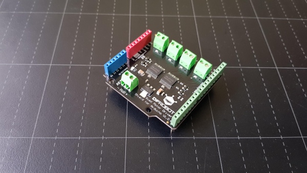
The driver shield includes two TB6612FNG motor driver chips with maximum output 1.2A continuous current on each channel. The module includes a built-in low voltage detection circuit and thermal shutdown protection circuit, which is safe and reliable.
You can check detail at product link and wiki page.
Step 4: Circuit Diagram
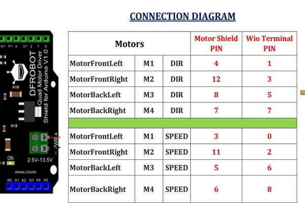
The motor connection is shown below:
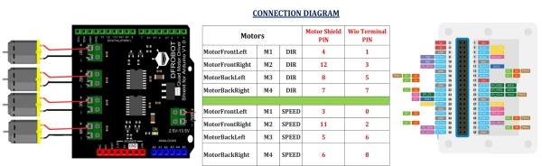
The quad motor shield need two signals to control one DC motor: DIR & SPEED. And the motor speed signals have to be connect to PWM pins of Wio Terminal, as follows:
- PWM0 (D0/A0).
- PWM1 (D2/A2).
- PWM3 (D6/A6).
- PWM4 (D8/A8).
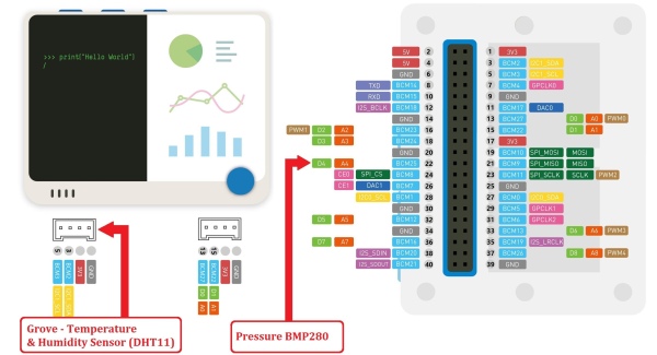
The DHT11 temperature & humidity sensor is connected to Grove I2C port & BMP280 pressure sensor is connected to pin D4/A4 of Wio Terminal.
Step 5: Build a Car Chasis
Firstly, I joined 2 pcs x PVC tees Ø42mm together to build a car chassis.
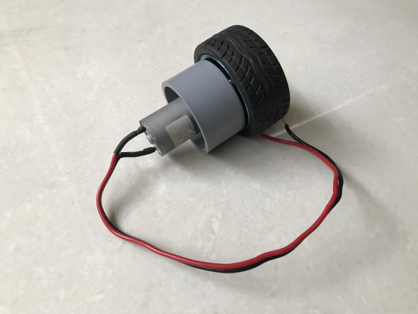
I measured and drilled holes on the 4pcs x PVC end caps Ø42mm which were used as motor supports. I soldered all power cables for 4 DC motors, mounted them on the end caps and attached hexagon motor couplings for wheels.
Drill some holes on the top of PVC chassis to mount battery holder, control boards and DC motor cables.
Step 6: Wheel Assembly
I attached all 65mm rubber wheels to motor shafts via hexagon motor couplings.
I didn’t have enough 4 wheels so I used 2 pulleys 80 teeth for two front wheels.
Four end caps motor supports were connected to PVC car chassis by 4pcs x pipes Ø42mm, length 65mm.
Thread all motor cables inside the PVC chassis and they come out through an opening drilled.
Install a steel plate between two PVC tees to ensure the chassis stays in place and alignment when it’s in operation.
Step 7: Baterry Holder
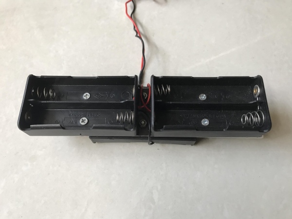
I cut a small acrylic sheet, dimension 180 x 40mm, drilled holes amd mount 2pcs x one slot & two slot battery 18650 holder on it.
All batteries including their plastic holders were hidden inside the PVC straight connector Ø60mm.
I covered this PVC battery holder by end caps and mounted one ON/OFF power switch at the back of end cap Ø60mm.
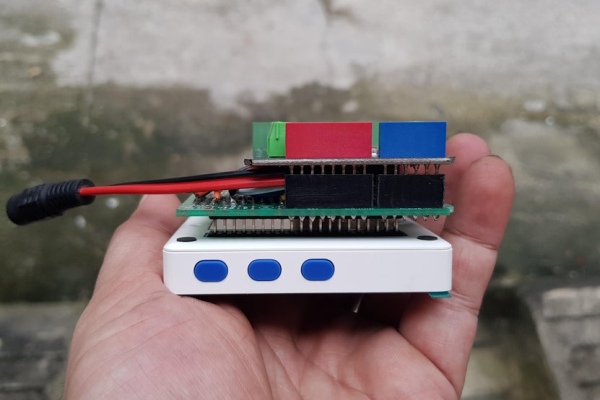
Step 8: Soldering Protoshield and Battery
I soldered 2 row x 20 pin male headers on the Protoshield PCB bottom. It was used to connect to Wio terminal female header.
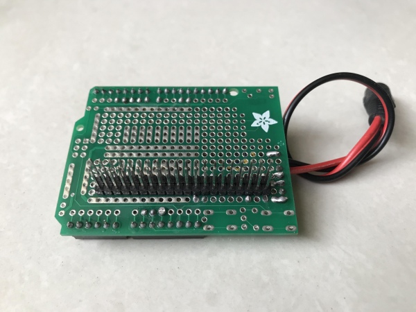
On the Protoshield top, I soldered all female headers corresponding to the male headers of Quad DC Motor Driver Shield. Then I soldered all control wires from Wio Terminal to the Motor shield following the schematic on the previous step.
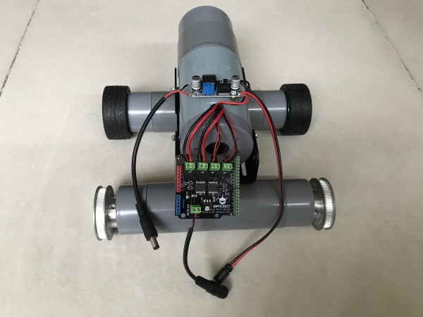
Connect Protoshield with Wio Terminal and motor shield. It looks like this.
I used 6pcs x 18650 rechargable batteries which were divided into 2 parallel groups and each group with 3 batteries in series. When fully charged, the output voltage was about 12VDC. To power 5VDC to the Wio Terminal and the motor shield, I used a step-down power supply module LM2596.
Step 9: Assembly & Connection
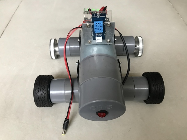
Install battery holder on the chassis and place LM2596 module on top of PVC battery holder.
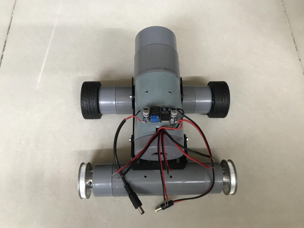
Connect all motor cables to quad motor shield terminals.
Install DHT11 and BMP280 sensors on the PVC battery holder.
To mount Wio Terminal and motor shield, I used one other aluminium angle and acrylic sheet.
Insert 6pcs x 18650 batteries into their slots.
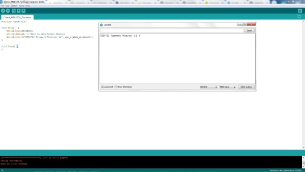
Step 10: Flashing RTL8720 Firmware for Wio Terminal
To update the latest firmware for the Wireless Core Realtek RTL8720 on the Wio Terminal, we can refer to this link:
I have updated RTL8720 firmware to version 2.1.3.
Some libraries for Bluetooth were also installed into Arduino IDE.
Step 11: Programming
The project code is available at my GitHub.
a. Car Controlling
The four-wheel car is controlled by Bluetooth via Blynk software. You should get your own “Auth Token” in the Blynk App.
Each motor has the following properties:
typedef struct
{
  int SPD_PIN;    // Speed Pin
  int DIR_PIN;    // Direction Pin
  int SET_SPEED;  // Speed to be set
} Motor;
Car control is performed on the Blynk App by virtual pins.
BLYNK_WRITE(V1)
{
  Forwardcmd_V1 = param.asInt(); // Get value as integer
  if(Forwardcmd_V1)
  {
    RC_Car_Forward();
  }
  else
  {
    RC_Car_Stop();
  }
}
And the movement command is also printed accordingly on the Wio Terminal screen.
void RC_Car_Forward()
{
  // Set car Direction
  digitalWrite(MotorFrontLeft.DIR_PIN, 0);
  digitalWrite(MotorBackLeft.DIR_PIN, 0);
  digitalWrite(MotorFrontRight.DIR_PIN, 0);
  digitalWrite(MotorBackRight.DIR_PIN, 0);

  // Set car Speed
  analogWrite(MotorFrontLeft.SPD_PIN, MotorFrontLeft.SET_SPEED);
  analogWrite(MotorFrontRight.SPD_PIN, MotorFrontRight.SET_SPEED);
  analogWrite(MotorBackLeft.SPD_PIN, MotorBackLeft.SET_SPEED);
  analogWrite(MotorBackRight.SPD_PIN, MotorBackRight.SET_SPEED);

  // Show "FORWARD" command on LCD screen
  Car_Image.createSprite(WIDTH, HEIGHT);
  Car_Image.fillSprite(TFT_BLACK);
  Car_Image.setTextColor(TFT_MAROON);
  Car_Image.setFreeFont(&FreeMonoBold24pt7b);
  Car_Image.drawString("FORWARD", 70, 6);
  Car_Image.pushSprite(0, (HEIGHT/2) + 1);
  Car_Image.deleteSprite();
}
a. Local Weather Reading
In my program, weather information is updated and displayed on the Wio Terminal screen regardless of whether my four-wheels car is connected to Blynk or not. I used “BlynkTimer” to configure the interval reading of temperature & humidity, pressure and light sensors.
  // Set-up 2 second intervals between BMP280 readings
  timer.setInterval(2000L, myTimerBMP280);
  // Set-up 3 second intervals between DHT11 readings
  timer.setInterval(3000L, myTimerDHT11);
  // Set-up 4 second intervals between Light sensor readings
  timer.setInterval(4000L, myTimerLight);
For example, the pressure sensor BMP280 is read every 2s, then its data is sent to Blynk screen ,as well as, displayed on the Wio Terminal LCD screen.
void myTimerBMP280()
{
  readPressure();

 // Send to Blynk
  Blynk.virtualWrite(V6, pressure/1000);

  // Show actual pressure on LCD screen
  Car_Image.createSprite(WIDTH/2, HEIGHT);
  Car_Image.fillSprite(TFT_BLACK);
  Car_Image.setTextColor(TFT_RED);
  Car_Image.setFreeFont(&FreeMonoBold12pt7b);
  Car_Image.drawString(pressureStr, 2, 12);
  Car_Image.pushSprite(0, (8*HEIGHT/2) + 1);
  Car_Image.deleteSprite();
}
And the actual surrounding pressure is read and processed as follows:
void readPressure()
{
  // Read the pressure from BMP280
  pressure = bmp280.getPressure();
  // Convert to String for showing on the LCD screen
  pressureStr = "P:" + String(pressure/1000) + "kPa";
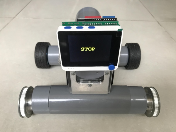
Step 12: Blynk & Wio Terminal Screen
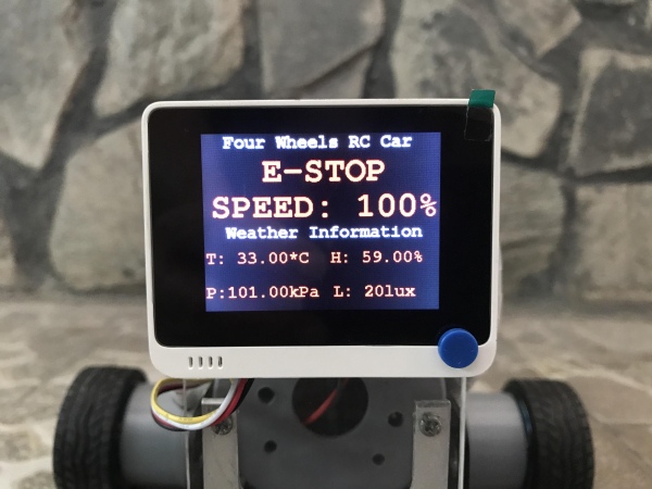
⦾ Below the header “Four Wheel RC Car“, it shows:
- Status of command FORWARD/ BACKWARD/ TURN RIGHT/ TURN LEFT/ STOP / E-STOP.
- Speed indication in percentage.
⦾ Below the header “Weather Information“, it shows the following data:
- Temperature (T).
- Humidity (H).
- Pressure (P).
- Light (L).
b. Blynk screen on smart phone.
The Blynk HMI shows weather information and car control commands in a way that correlates with the Wio Terminal screen.
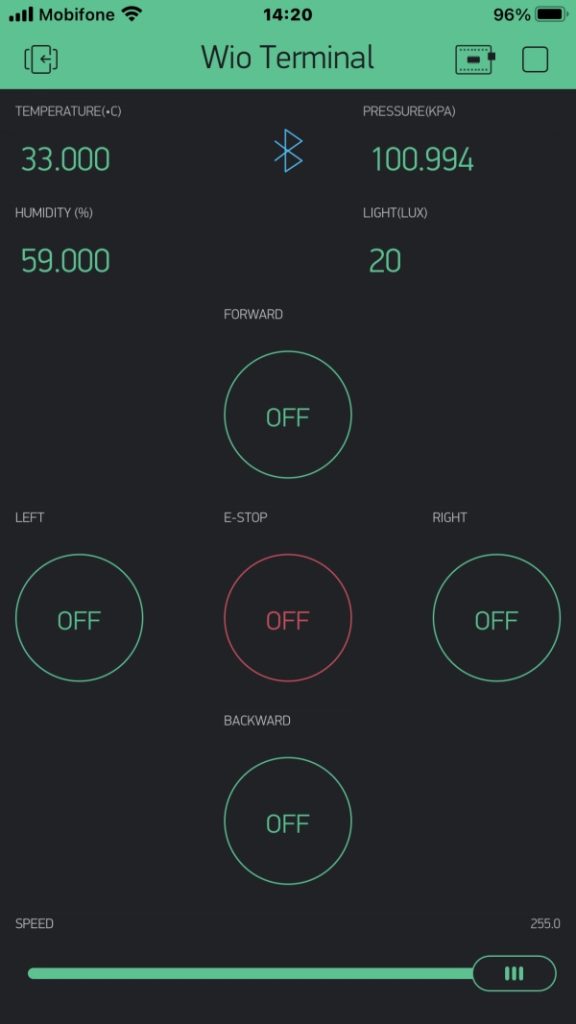
I used virtual pin in Blynk for E-Stop button. But it is better to program one of built-in physical buttons on the Wio Terminal as a E-Stop button, in case something goes wrong.
Step 13: Testings
I did first testing without weather station to adjust the speed of 4 motors which ensure that the car can move in straight line. We can calibrate them with speed ratios among 4 DC motors in the program.
Because Wio Terminal has a built-in accelerometer sensor, so it can feedback whether the car moves when we send a command to run.
Step 14: Conclusion
We can use this four-wheels car in stationary or mobile mode. It can be put on the table as normal local weather stations.
Thank you for reading my works. Thank to JLCPCB, Seeed Studio, DFRobot for for supporting me on this project!!!
Source: The Local Weather Station on a Four-Wheels Bluetooth Controlled Car
-
How is the car controlled remotely?
The car is fully functional and controlled via Bluetooth using the Blynk software application. -
What microcontroller is used for the project?
The project utilizes the Seeed Wio Terminal, which is a SAMD51-based microcontroller with wireless connectivity. -
Which sensors measure the weather data?
The system uses a Grove DHT11 sensor for temperature and humidity, and a Grove BMP280 sensor for air pressure. -
Can the car move in all directions?
Yes, the car can move forward, backward, turn left, and turn right using its four DC motors. -
Where is the weather data displayed?
Data is shown on both the Wio Terminal LCD screen and the Blynk HMI screen on a smartphone. -
What power source drives the motors?
Six 18650 rechargeable Li-ion batteries are used to provide approximately 12VDC to the motors. -
How is the voltage regulated for the controller?
An LM2596S 3A adjustable step-down DC-DC power supply module converts the battery voltage to 5VDC. -
What material is used for the car chassis?
The chassis is built using PVC pipes (Ø42mm and Ø60mm) connected with tees and end caps. -
Does the car need internet to read weather data?
No, weather information is updated and displayed on the Wio Terminal screen regardless of the Blynk connection.