-This project was conducted as part of the Computational Design and Digital Fabrication seminar in the ITECH masters program.-
Know someone overly extroverted and who just can’t stay quiet? This guide will show you how to create an inflatable necklace that chokes the person wearing it whenever he tries to speak…
Joking! Let’s not choke anyone and do this project just for fun!
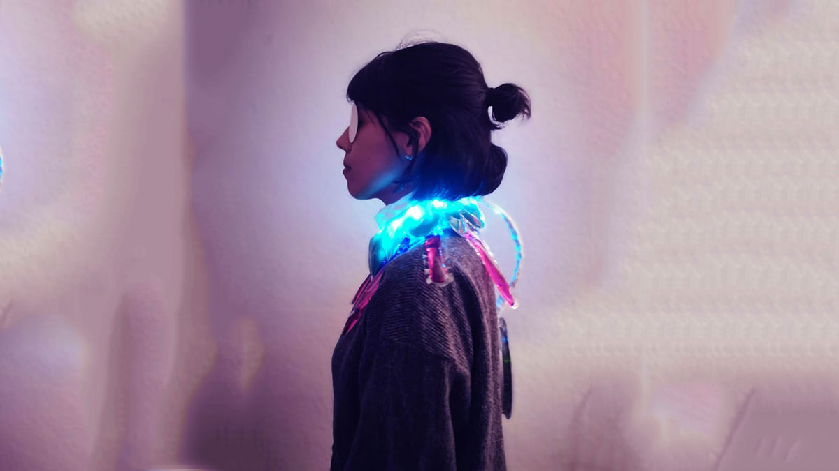
The necklace consists of two PVC cushions filled with liquid and an inner PVC cushion that inflates and lights up thanks to a vacuum pump and a LED strip. On the back hangs a control box that houses the microcontroller, batteries, vacuum pump and all the electronics needed.
The aim of this project is to create a wearable, easily made by anyone with readily available materials. The templates for the parts and the codes are provided.
Read on to see how you can make it…
Step 1: Find Your Materials
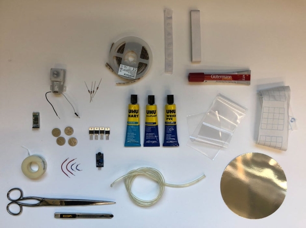
Electronics
- Arduino nano
- USB micro to USB data transfer cable
- 12v RGB LED strip
- 12v vacuum pump
- Sound sensor
- 1 Push button
- Breadboard (85mm x 55 mm)
- Jumper wires
- 1 9v battery
- 4 MOSFET
- 3 1 kΩ resistors
- 1 2.2 kΩ resistor
- 1 Diode rectifier
Materials
- 1000 mm x 1000 mm PVC film
- Liquid soap in the colors of your preference
- Paper (baking paper or tracing paper)
- Double sided tape
- 4 m ribbon in desired color
- Acrylic sheet 600 mm x 600 mm x 2mm.
- Paper or cardboard in any color.
- Double sided tape
- PVC tube (5mm diameter)
- PCV glue
- Acrylic glue
- Tape
- 2 Pressure buttons
Tools
- Iron or heatgun
- Scissors
- Pliers
- Printer
- Laser cutter
- Funnel
Step 2: Create the PVC Cushions
2.1 Templates
The necklace consists of three PVC cushions. In order to make them, firstly you will need to print the templates provided. After printing the templates on wax paper the layers labeled as “Inner”. After cutting everything you will have 3 pieces cut, one per cushion.
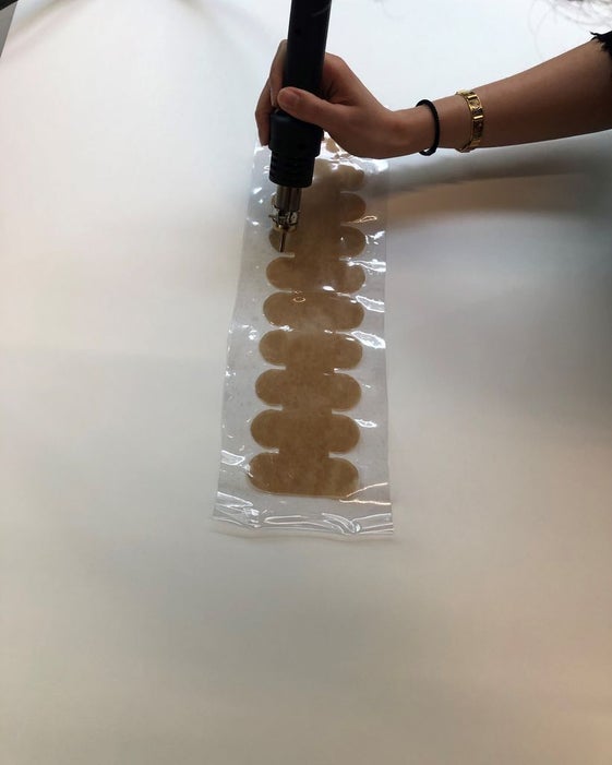
2.2 Weld the layers
To create an airtight PVC cushion, you must weld it with heat. You start by placing the inner pieces between the PVC layers, and a piece of paper and cloth on top. Now with your iron in a low setting, go over your layers, constantly checking if the PVC layers have attached to each other. This is a slow process since you don’t want to burn the PVC using a high setting. The wax paper in between layers help so the PVC will not attach on those areas and will create the desired shaped cushion.
If you have access to a heat gun, you can use this instead of an iron. The only difference is that after placing the inner layers of wax paper. you apply the heat directly to the PVC (You don’t need the protection on top).
After you have your welded shapes, you cut the PVC following the outline of the template.
Using pliers remove the wax paper in between the PVC layers. Be very careful you don’t want to make a rip on the PVC.
2.3 Filling and sealing
Cushion 1 and 2 need to be filled with a thick liquid such as shampoo or any type of liquid soap. To fill the cushions, place a funnel on the open end of the cushion and add the liquid.
After the cushions are full, clear the opening from any traces of soap and seal it with PVC glue.
Cushion number 3 is the one that is going to inflate, to achieve this, place a tube on the opening of the cushion and seal it with PVC glue. To finish off, glue ribbon on the edge, to hide the opening and to being able to attach a pressure button on each lapel.
Step 3: Ardunio Code
The system is straight forward. When you turn on the system the necklace light ups and a sound sensor starts working. The sensor is going to detect when the person wearing the necklace is speaking and this is going to give the signal to the pump and the led strip.
When noise is detected the led strip starts blinking going from white light to green in 5 steps.
int redPin = 10;
int greenPin = 9;
int bluePin = 11;
int pump = 5;
int vol= A0;
int val1 = 0;
int val2 = 0;

void setup()
{
  pinMode(redPin, OUTPUT);
  pinMode(greenPin, OUTPUT);
  pinMode(bluePin, OUTPUT);
  pinMode(pump, OUTPUT);
  pinMode(vol,INPUT);
  Serial.begin(9600);
<p>}</p>void loop()
{
val1 = analogRead(vol);
  Serial.println(val1);
  delay(1);
  val2 = analogRead(vol);
  Serial.println(val2);

if (val2-val1>12 || val1-val2>12)
  {
  digitalWrite(pump,HIGH);
  setColor(255,255,255);
    delay(1000);
  setColor(255,191,191);
    delay(1000);
  setColor(255,127,127);
    delay(1000);
  setColor(255,64,64);
    delay(1000);
  setColor(255,0,0);
    delay(1000);
}

else
  {
    digitalWrite(pump,LOW);
    digitalWrite(redPin, HIGH);
    digitalWrite(greenPin, HIGH);
    digitalWrite(bluePin, HIGH);
  }
}

void setColor(int red, int green, int blue)
  {
    analogWrite(redPin, red);
    analogWrite(greenPin, green);
    analogWrite(bluePin, blue);
  }
Step 4: Wiring Up
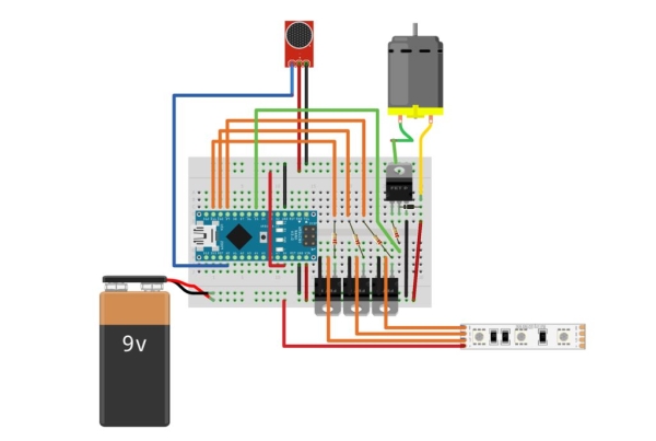
Attach the Arduino Nano to a Breadboard (85mm x 55 mm). The LED strip and the pump run at 12 v. but with a 9v battery is enough, so start by running a 9v power supply to one rail of the breadboard.
To control the led strip that needs more electrical current than the microcontroller can supply, you need a circuit that can boost the power from the 9 v battery. To do this place a transistor to the breadboard. Connect the base of the transistors to a 1 kΩ resistor and then to any PMW pin of your Arduino since we need analog results to modulate the intensity of the LEDS.
Connect the collector of the transistor to the red light of the led strip and run a wire from the emitter of the transistor to the ground rail of the breadboard.
Build that same circuit two more times for the green and blue light of the led.
Finally Connect the power of the led to the positive power rail if the breadboard.
For the 12v pump we need a similar arrangement. In this case we are going to add a diode to avoid any kickback from the energy source to the Arduino.
Connect the Vin pin to the positive energy rail to supply your Arduino.
The sound sensor works with 5v, to do so, connect the positive side to the 5v pin from the Arduino and then connect the analog end to an analog pin and the negative to the ground rail.
Source: The Cold Shoulder