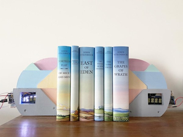
Since more and more of us are working from home, we are all increasing our engagement with our screens (looking at you, Zoom meetings). For myself, when I am taking a break from my computer screen I end up doing other things in my apartment and a large amount of the time, I don’t keep my phone on me. Naturally, this leads to me, a chronically late person, rushing to make my meetings, digitally and in person, when I realize that time has escaped me. So I thought, it would be great if I had an object in my home that told me how many minutes I have left to relax without needing to check my phone.
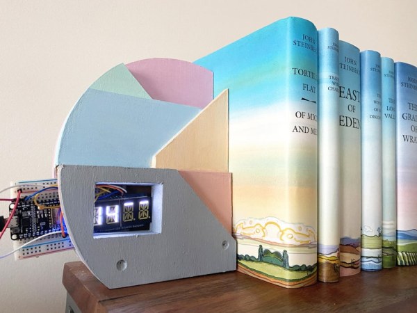
With this tutorial, you can make your own LED display bookend (or sculpture, up to you, whichever way you want to display the product in your home) that connects to your Google calendar. The LED display shows how many minutes you have left until your next event on your Google calendar begins.
Before starting this tutorial, please reference Becky Stern’s Arduino class to ensure you have a good understanding of Arduino.
*Please note that due to the communication between Google Calendar, Adafruit.io, and IFTT, there is a 4-minute delay with the display to be accounted for. So when the timer says “4” that means your meeting is starting then and not at 0.
Please let me know if anyone has any tips to make adjustments to the code to account for this issue. Thank you!
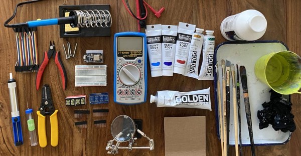
Step 1: Detailed Supplies List
- NodeMCU ESP8266 (or you can use the Feather Huzzah ESP8266 with stacking headers, but the pins are different) (x2)
- 4-digit 7-segment alphanumeric display with LED backpack (x2) (this dual display is also a good alternative and comes in a pack of 2)
- Short Feather Male Headers
- Soldering iron and solder
- Breadboard wiring bundle
- Perma-proto half-size breadboard (x2)
- Flush diagonal cutters
- Wire strippers
- Multimeter (optional but handy for troubleshooting)
- Third hand tool
- Solder sucker
- Micro USB cable (x2)
- 4 1/2″ MDF layers
- 8 1/4″ MDF layers
- Laser cutter
- Wood Glue
- Screws of your choice
- Liquitex Paints (spray paint can be used here for a more even texture. I handpainted mine because I had acrylics on hand.)
- Liquitex Gesso
- Liquitex Titanium White
- Liquitex Ultramarine Blue
- Liquitex Burnt Umber
- Liquitex Yellow Ochre
- Liquitex Alzarin Crimson
- Liquitex Cerulean Blue
- Liquitex Viridian Green
- Paintbrushes
- Old rags
- Paint Container
- Butcher Tray Palette
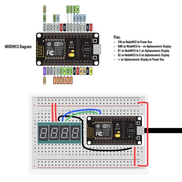
Step 2: Circuit Diagram & Code
Before we start on the form, let’s make sure that your circuit works. You can download the Arduino files and make small adjustments such as inputting your WIFI information and your Adafruit.io information.
To begin, let’s start with the online setup.
- Log into Adafruit.io. Under Feeds, make a new feed called “Google Calendar Events”.
- Once the “Google Calendar Events” feed is made, go to “Feed Info” and change the Key to “gcalendar” (case sensitive).
- Log into IFTT. Make an Applet. Under If this, choose the Google Calendar “Any event starts” and follow the steps until it is confirmed connected to your If this applet.
- Go to the Then that section of your applet and select Adafruit. Follow the steps until completion and under Feeds connect to: “Google Calendar Events”.
- Choose the 30 minute time interval under “Time before event starts” and under Data to Save write “30”. Once you have finished that Applet, rename it “30 If any event starts on the calendar, then Send data to Google Calendar Events Feed”.
- Make an applet for each of the following time intervals (0, 15).
- Test your feed to see if the Google Calendar events sync to your Adafruit account.
- Create a new event in your Google Calendar within a 35-minute time frame to give the applets some time to begin communicating.
- Open your Adafruit.io “Google Calendar Events” feed to see if the 30-minute point is registered in the graph. Check back in 15 minutes to see if the 30-minute point is registered.
- Once confirmed that your Adafruit and IFTT work is synced, let’s go to Step 3: Circuit Construction and wire your NodeMCU and Alphanumeric display based on the circuit diagram above.
Once you have wired your circuit based on Step 3 please return here for testing.
- Connect your NodeMCU to the Internet via your Arduino software.
- Download the code in the Arduino file.
- Open this code in the Arduino and upload the code to your NodeMCU. Don’t forget to input your Adafruit username and key from your Adafruit.io account.
- Open the Serial Monitor to see if it is properly connected.
- Test your circuit to see if the events display properly by repeating step 10, but this time take a look at your LED display to see if the time adjusts accordingly. If it does then great! You’re all set to get started on the form of the bookend.
Step 3: Circuit Construction (Prototype to Soldered)
Please note that the first image is my initial prototype and the second image is the actual prototype for this project.
I began my circuit by using the diagram seen in Becky Stern’s Wifi Weather Display tutorial but using only one Neopixel and outfitted for the NodeMCU instead of the Feather. Based on her diagram, I originally thought that I would be stacking the display on top of my NodeMCU ESP8266 board, which is why I created specific dimensions in my bookend. However, based on my beginner understanding of the parts, when I actually began constructing the circuit, I realized that the display would have to be next to the NodeMCU since I did not have stacking headers on my NodeMCU board. I also decided to forgo the neopixel at this time.
Also, I originally planned on creating my circuit with the 4 Digit Seven Segment LED Display. However, when I soldered the pieces together, I accidentally soldered the display upside down on the board. Since it would be too difficult to have that cleaned up well enough to create a clear connection, I switched to the Alphanumeric Display in the materials list, which ended up being easier to understand for myself.
To create my circuit I did the following:
- I assembled the alphanumeric display using my soldering equipment. This article is the one I used to guide my assembly of the display.
- Once the display is properly soldered together, attach the display next to the NodeMCU on the breadboard.
- Then begin wiring the circuit using the diagram on Step 2.
- Check that your wires work by using the multimeter. For beginners, this is a good video showing you how to use a multimeter.
- Once you have confirmed that your wiring works, go back to Step 2 and complete the rest of the software setup.
Step 4: Form and Material
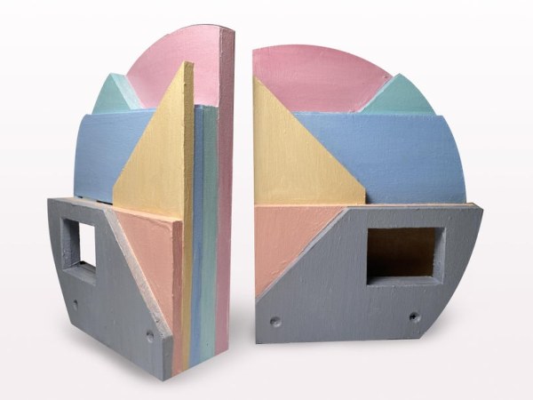
Once you have confirmed that your circuits are connected, let’s start with the form of the bookend.
- First gather up your MDF. I laid out my pieces using the attached Illustrator files as the layout for the team that helped me with constructing my MDF layers and cutting them out with a laser cutter.
- So first step in making the form is to gather the MDF pieces and cut them out based on the Illustrator file called Bookend MDF.
- Once you have cut down your MDF layers to the correct sizes, it is time to laser cut the pieces. If you have access to a laser cutter, cut it out based on the curvature of the Illustrator file Bookend Laser CNC. You also do not have to cut out the bookend to create the curved look. To make the mirrored image of this bookend, please use the same dimensions but flip where the cutouts will be.
- Originally when I laid out the form, I thought I would be able to stack the display on top of my NodeMCU. Since this is the first time I have worked with these components, I miscalculated the dimensions and the final product has half of the breadboard sticking out of the form. So, for those of you trying this, I would suggest making adjustments to the cutting out of the square in the layers to fit in the whole length of the breadboard and using a dual alphanumeric display so the circuit isn’t poking out.
- The sketched looking diagram shows how the layers are to be stacked up. Stack each layer with wood glue in between each piece. Be sure to clamp them down to keep them in place.
- Then for extra measure, you can drill two holes but not going all the way through and screw in two screws to keep the layers together.
- Once the bookend is solidly one piece, you can start painting. Please refer to the “Adding Color” section if you would like to use this color palette.
- Once you finish painting, set to dry, and once dried, put your circuit into the open space of the bookend.
- Plug into a power source and you are good to go!
For a better understanding of laser cutting please take a look at this tutorial and for a better understanding of the MDF material, please look here.
ADDING COLOR:
I handpainted my project since I am in a small apartment with no outdoor space and a rooftop that management would not particularly be thrilled about me spray painting on. I had never painted on MDF before so I used this article as a reference. Feel free to paint in any way you see fit.
Start with 2-3 layers of Liquitex Gesso. Then proceed with the following layers. The mixes to get the paint colors for each layer are as follows:
- Grey:
- Liquitex Titanium white, Ultramarine Blue, and Burnt Umber
- Pinkish Peach:
- Liquitex Titanium white, Yellow Ochre, Alzarin Crimson
- Dark Cream:
- Liquitex Titanium white, Yellow Ochre
- Light Blue:
- Liquitex Titanium white and Cerulean Blue
- Mint Green:
- Liquitex Titanium white and Viridian Green
- Light Pink:
- Liquitex Titanium white and Alzarin Crimson
Step 5: Celebrate and Call to Action
Thanks for reading my instructable! Try it out yourself.
As this was my first combined woodcut / IoT project, please feel free to let me know better ways to improve this project for the future. If you do try it I hope this helps you be more on time for your calendar events. It’s definitely helping me out.
Source: The BookMinder: a Bookend Meeting Countdown Device