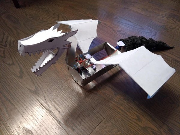
ROOAAARR!! Before you learn how to train your dragon, you need to first obtain a dragon, and there’s no better way than to make it yourself! This guide will explain the steps I took to create a scale model animatronic dragon, and in doing so I hope you might also learn how to follow similar steps to make your own if you so choose.
Here’s a video preview of the final result!:
The St. George legend famously portrays St. George protecting a nearby village from a giant serpent/dragon, where he is often depicted riding his white horse and stabbing the dragon with a spear/lance. I had made a full size animatronic dragon for my church theatre team two years ago, but sadly the electronics were not on during the real performance! Aiming to redeem myself with an improved version, I designed and fabricated this prototype to test out my new ideas and amass buy-in for supporting building the new full version in the near future.
I designed my dragon to have the following features:
- Dragon shall be fully Bluetooth controlled
- Dragon shall open and close its jaws
- Dragon shall rotate its neck
- Dragon shall flap its wings
- Dragon shall whip its tail back and forth
- Dragon shall walk on its legs
- Dragon shall spray blood when the wing is disconnected (red colored water sprayed via USB pump and tubing)
Note that this kind of animatronic work is just as much an artistic work as it is a mechanical, electrical, and software engineering feat. Feel free to adjust the steps as you would like for your own preferences and resources available!
[Disclaimer: I did not actually finish the entire dragon per my original plans, as I stopped short of adding the walking legs and USB pump spray. This guide describes the steps I took to complete the rest of the dragon, and I would follow similar approached to complete the rest. One day soon I’ll finish it completely and re-update this guide.]
Supplies
For this scale model build, I decided to go with lighter materials to avoid weight from ruining the functional movements of the different mechanisms. I also owned much of what is on my list, so feel free to adjust with what you personally own already, or consider purchasing those items as well. Thus, here is roughly my supply list:
* Note: Prices have been rounded up and excluded tax for simplicity
– 1 ft x 2 ft Aluminum Sheet Metal – Home Depot – $11
– 10x SG90 9G Micro Servos – Amazon – $19
– ESP32 Microcontroller & PCA9685 Servo Driver Board (already owned these, might be out of pocket expense for others)
– 8x AA Batteries
– USB water pump & Plastic tubing for pump (I already had these from my last dragon attempt, this would be an extra out of pocket expense, but the pump and tubing are pretty inexpensive)
– Cardstock paper, cardboard (you can use index cards instead of sheet cardstock)
– Duct Tape, Hot glue (a hot glue gun is extremely useful to own, strongly recommend getting one!)
– Aluminum foil
My Total out-of-pocket cost: $30
Step 1: Create the Concept and Design
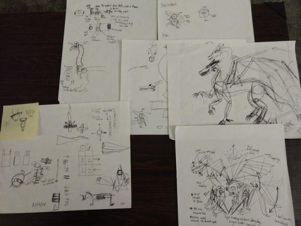
The first and arguably most important phase of the project is the concept creation and design stage! Proper systems engineering dictates that majority of defects/problems that cost more time/resources to fix can be prevented more easily when addressed earlier in the design.
While it is motivating to draw the dragon’s aesthetic design for the final look desired, focus also on the main mechanisms that will provide the intended motions:
- How will the jaws move? Both top and bottom jaws moving or only one side?
- What will be the main mechanical device used to move the jaws together? Gears? Springs? Clothespin?
- What mechanism will be used to move the wings? Will the motion be smooth as desired?
- How will the tail be attached?
- How will the dragon walk? What is the intended walking gait?
- Where will the blood spray tube and pump go?
- Where will the red water reservoir sit?
- Where will the rotation in the neck occur? Near the base of the neck or halfway down the neck?
These questions and many more should be pondered and considered, and the resulting ideas should be captured as sketches and diagrams. You will likely need to revise these several times throughout the project, so don’t feel like you have to commit to the ideas once drawn. It’s okay to have many scribbled out ideas if they do not work later on, but always better to have them on paper than floating in your mind.
Step 2: Construct the Main Mechanisms
Once you feel comfortable with a design, start fabricating the main mechanisms for movement.
For the neck, I simply attached a disk to the top of a servo horn, as the radial motion is already well-suited for neck rotation. For the tail, a similar approach was taken in using the radial motion, but the aluminum piece was bent at a right angle so that the tail would attach perpendicular to the axis of motion.
The jaws were trickier to create, as I desired to have both jaws move in opposite directions when the mouth opened and closed. Two identical gears interfacing with each other accomplishes this, and 3D printing these can make the job simpler. However, to save time from trying to find/make identical small gears, I took apart some gears from a cheap clock gear train and made my own bracket to hold the pieces together. If you have the time and/or skill to find or make the gears as a 3D printed part, I would recommend it to ensure quality movement with ease.
The wings mechanism was by far the hardest for me to fabricate. I’ll explain more in the next step, as sometimes redesigning is necessary.
Step 3: Redesign Mechanisms As Needed Until Reliable!
Sometimes designs work as intended, and sometimes they do not. For a professional engineering job/product, this truth emphasizes using all systems engineering tools possible to thoroughly vet the design before proceeding further in development. For a hobby project like this dragon, you should give yourself permission to run into failures and learn the lessons from them as a beneficial experience.
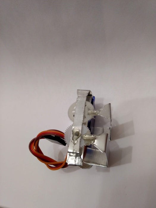
For my wings mechanism, I originally planned to use a counterweight for the wings to keep them lifted. Then I wanted to have a servo pull the weight up – thus letting the wings gently lower – until a point where it purposely looses contact for the counterweight to fall back down and lift the wings up again. Later on I switched ideas to make use of a Scotch Yoke mechanism to turn circular/radial motion into a linear/reciprocating motion. The first few pictures show my attempt at doing so.
While the Scotch Yoke mechanism I haphazardly fashioned worked for some time, eventually there came to be several mechanical defects. The vertical piece would not stay straight during the motion, which tilted the yoke part grossly outwards, preventing the screw-axle from moving, and…. overall the motion progressively degraded and led to burning out one of the servos from the excessive strain. But you should not let these failures set you back permanently, we must always strive to keep moving forward!
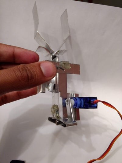
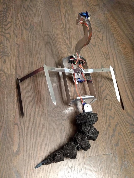
Even though this happened at the very end of the project when I was trying to program all the servos, I had to redo the wing mechanism completely. I went with a piston-like double-linkage approach, where the piston ran inside a round channel that helped maintain straight alignment of movement. The double-linked helped to easily translate the radial motion to linear motion without excessive strain or friction on the servo or linkages. Additionally, the servo did not even have to move the full range of its motion to translate the linkages for the full flapping effect. The end product was immensely better than before, and the final movement could not look any more awesome!
Step 4: Construct the Body Structures (body, Neck, Legs, Etc.)
Now that the main mechanisms have been addressed, they need to be assembled to each other in the frame of the body. Time to add some curves to your dragon!
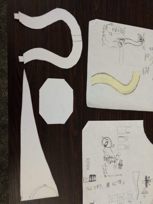
When creating the larger parts of the dragon’s structure, I found it helpful to first trace and cut out the parts onto cardstock (see first picture). This lets you ensure the shape and size of the parts are proportional to the desired dragon aesthetics and fit the rest of the mechanisms that must be attached. For the body, I needed to create a front and back panel shape that could center and conceal the wings mechanism, so I arrived at a necessary dimensions of 4 inches wide and 3 inches tall. I chose an octagon shape so that when adding final touches in the end, the body would not look box-like and would appear rounded and natural. Other considerations you might want could include having an access panel for quick post-project electrical fixes/battery swaps, magnetic attachments for limbs to facilitate easy transport, etc.
Once the parts are traced on the aluminum, I used metal shears (like a thinner needle-nosed tin snip) to cut the metal in the shapes I drew. Curled corners can be straightened/flattened with needle-nose pliers, and you can even round sharp edges with the metal shears. I enjoyed using this pair of metal shears. Be sure to purchase one that can handle your gauge of aluminum/sheet metal that you selected.
Attach the main mechanisms to your body structure using either hot glue (works well for quick and easy attachment, but work fast because the metal cools the glue very quickly!) or using metal screws/bolts and nuts. You can even use pop rivets if you have a rivet gun/riveting tool. I preferred using hot glue also because it is not too hard to remove if you mess up and parts can then be reconnected properly. Be sure to account for making attachment brackets for all mechanisms, including the wings-to-body bracket piece.
Step 5: Create an Articulated Tail
The tail was a fun part of the dragon to make! I was inspired by several online designs and YouTube tutorial videos I had seen during the concept planning, settling on the design above.
To make my tail above, I first started with a tail template traced and cut from cardstock. I traced this pattern onto a piece of cut denim fabric, which was a strong cloth that could be used as the middle vertical center of the tail. The fabric allows for the tail to be flexible and naturally bending in the middle.
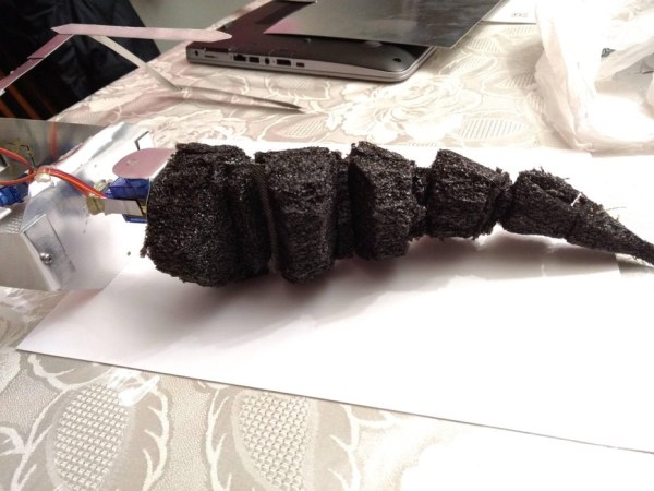
To give the tail its volume, I then attached pieces of dense foam I had lying around from my 3D printer’s original shipping packaging (EVA foam or similar works fine too, non-rigid materials like cotton balls discouraged). The foam was cut into the tail pattern shape, and then I rounded it along the long dimension to give it a natural rounded look. You can use a utility blade or a serrated knife to make the cuts (I found it very easy to slice using the serrated knife, felt like shaving a cucumber!). Hot glue can be used to attach the foam to the fabric, and then the first tail segment to the tail mechanism.
The articulation comes from attaching the foam to the fabric, but also having diagonal vertical cuts on each segment to allow for them to bend towards each other. From a top down view, this is almost like cutting out triangles with the top points of the triangles at the center of each segment on each side. Again YouTube video tutorials will help here, but hopefully what I am describing is evident in the above pictures. If the articulation is too floppy, too much gap exists between segments, and that can be filled back in with extra foam. If too stiff and not moving enough, cut away a little more foam until the joint moves as desired. Keep the extra foam you cut away just in case you need to make adjustments later in fixing the articulation.
Step 6: Add the Power of Flight With Wings!
Once the flapping mechanism has been worked out and attached to the body, it’s time to feed the dragon some Red Bull and give it wings! (don’t get any liquids near this project in reality, you will regret it)
To keep the wings light, avoid shaping the whole wing out of aluminum, and instead make just the bones/tines from the metal. The rest can be fashioned decoratively using cardstock or even plain printer paper or aluminum foil. I found that a bend of about 135 degrees at the elbow/crook of the wing gives it a bit more character than just a plain flat wing. You could go further and add more joints/bends to the wings, just be sure that all joints are strongly supported if using multiple metal pieces. Hot glue helps to avoid adding the weight of heavier metal screws/nuts and bolts. Tape will not work to hold the metal wing pieces together as it most certainly will come apart upon flapping. If creating pointy-looking tines, be careful to round them out using the snips or a metal file, or else you WILL cut yourself/others or nearby furniture on these wings.
Step 7: Wire the Electronics
Now that the mechanical side is nearly complete, time to focus on the electrical side – where all the magic happens. The animatronic aspect is fairly straightforward: movement requires actuators, and the actuators all get connected to a driver board, which then connects to the main microcontroller. Sensors can be added as you wish, such as an IR or ultrasonic sensor in the nose/snout to sense a person/hand and then roar its jaws, etc., but I chose not to add any for now.
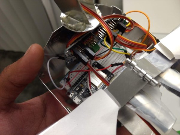
The connections I have shown were to connect all my SG90 micro servos to the PCA9685 servo driver board. This handy little board can be further chained to control up to 992 PWM outputs, but even one board lets you control up to 16 individual servos in parallel. The board has its own timer circuit and operates over I2C protocol, so just 4 wires connect back to the ESP32 microcontroller. See the code in the next step for an example of how to use this board with the Arduino library and ESP32 board.
The ESP32 board and PCA9685 also should get their own power sources separately. Servos have a higher power draw when moving, especially from being at full stop to starting motion. When servos cause this consequent dip in battery voltage from drawing more power, the microcontroller can lose its required voltage level and restart itself in the process, causing this endless loop of jitter or non-movement (look for constant resetting of the microcontroller lights as a symptom). Placing the servo driver board and the microcontroller on separate batteries will prevent this issue.
TIP: Connect your PCA9685’s Vcc pin to the 5V/Vin pin of your ESP32, as the 3.3V will not be enough to keep the driver board powered when operating all the servos in parallel.
TIP: When first testing the device, don’t immediately reach for the batteries and instead make portability the last step in wiring. Start with wired wall power via wall warts/adapters to bring in 5-6 volts with at least 2 amps of current (more current needed for the servos, microcontroller power can likely have a 1 amp source). Once all devices work as intended, make the switch to battery power. Make sure selected batteries can support the discharge rate and run time intended for desired operation, regular alkaline batteries may sometimes not be enough.
Step 8: Give Your Dragon Some Soul! (Add Covers and Details)
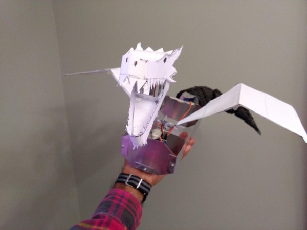
Now that most of your dragon is assembled and wired, time to add some flair! Give your dragon some soul and personality by adding decorative aesthetic details.
I used cardstock to create the basic head shape and jaws, attached via scotch tape (though in hindsight hot glue would have probably worked better here). The wing flesh was cut from regular printer paper, as it is a bit lighter than cardstock. Personally I ran out of time to cover the body, paint the tail, and color the dragon overall, but these steps can all be done at this time too. Ensure that decorative parts do not restrict or constrain the functional movements of the main mechanisms, make corrections if they do. Lighter materials work best to avoid weighing down the limbs and putting more workload on the servo motors. Be careful not to use heavy paints or tapes either; paint could also cause warping of cardstock/paper/cardboard parts.
Source: How to Create an Animatronic Dragon Model