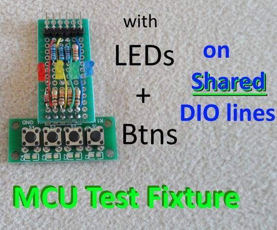
With this ‘Test Fixture’ and provided software you can test virtually any MCU with as little as 4 digital I/O lines (even only 2 is possible, all be it tricky) for project suitability and performance.
When I start a new project I don’t like hooking up a lot of wires before making any progress on what I actually want to focus on. So I built a 4 buttons and 4 LED fixture, utilizing only 4 or 5 DIO lines, which could quickly be hooked up to any MCU. I built a couple of versions, using a few different combinations of various types of buttons and LEDs I had on hand.
I further created this Instructable as I think that there are many out there would like to know how to successfully (without ill side effects) implement both a button and LED on one I/O line, as they may be running out of I/O lines in their project.
The 4×4 test fixtures and software can not only be used to test and evaluate potential MCUs for your project but also be utilized as a basis for your project(s).
The related Arduino sketches preform operations to exercise Buttons, LED operation and lighting levels, timing, interrupts, analog and digital I/O, EEPROM storage, USB-Serial I/O and optionally buzzer &/or speaker.
I also provide a MCU Performance Benchmark, giving “MCU Marks” for the number of times a second a standardized set of I/O and processing operations (simulated project) can be performed.
Step 1: Implementation of a Button and LED on the Same Line
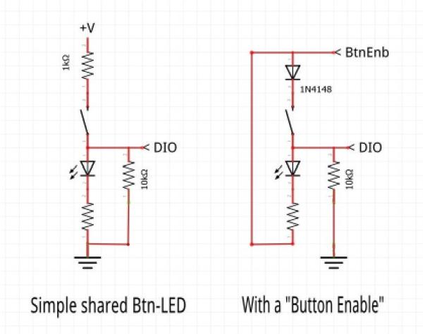
The schematic, above, shows a simple way to wire up a button with an LED on the same line.
Normally its shared I/O line will be set to output the state of the LED. To read the state of the button the I/O lines mode is set to input momentarily. This is so quick and if the button is not pressed the loss of energy to an LED will not be noticed. If, on the other hand, the button is pressed the related LED will be energized for an instant which with a high efficiency LED will be mildly noticeable as a very dim illumination if the LED is otherwise off. This side effect can only occur when you’re actively pressing a button, when the display is often in flux, and otherwise has no lasting operational effect. Below is code to support such an button/LED pair.
Sample code to read button on Shared I/O line:
    ledState = digitalRead(btn_PIN);
    pinMode(btn_PIN, INPUT);
    bntState = digitalRead(btn_PIN);  // read the Button input
    pinMode(btn_PIN, OUTPUT);
    digitalWrite(btn_PIN, ledState);  // reestablish the LED output state
For some of us and for some applications this is less than fully acceptable, especially when there is an additional I/O line that can be used to eliminate the effect.
The second schematic in the diagram shows a more advanced way to wire up a button and LED on the same line, which utilizes a button Enable line. Several I/O lines, each with a button & LED on them, can be supported with just one ‘button enable’ line. Below is sample code to support this arrangement.
Sample code to read button on Shared I/O line utilizing a “BtnEnable”:
    ledState = digitalRead(btn_PIN);
    pinMode(btn_PIN, INPUT);          // set I/O pin for INPUT
    digitalWrite(BTN_ENB, HIGH);
    bntState = digitalRead(btn_PIN);  // read the Button
    digitalWrite(BTN_ENB, LOW);
    pinMode(btn_PIN, OUTPUT);
    digitalWrite(btn_PIN, ledState);  // reestablish the LED output state
LED sub assemblies may be common Anode in nature rather than common Cathode, in which case the circuits would need to be in a sort of reverse polarity wiring and logic. Although I did not verify such an implementation, it should be doable.
Step 2: Components
For my first quick and dirty version I used these:
- 4 button assembly 4 Button module
- Led assembly (used only 4 of the 6 LEDs) LED Module on eBay
- breadboard 25 pt. 55 pt.
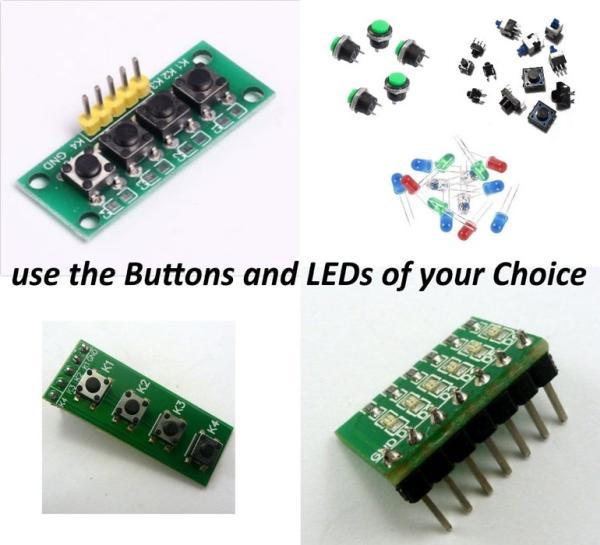
A more permanent version can be built up on a piece of breadboard PCB using what ever buttons and LEDs you have on hand (like mine seen in the next section). As mine is intended only as a test fixture I did not implement it with an enclosure in mind. For wiring details refer to the schematics and/or zoom into the photos.
For my second version (Test Fixture #2) I used these parts:
- 4 button assembly a little larger 4 button module
- individual LEDs, I had on hand, with appropriate current limiting resisters.
- perforated construction board (Link to a variety)
- pin header strip (find some here)
For both fixtures additional resisters, a 1N4148 diode, wire jumpers and etc. were used.
The only tools used were in the construction of my second fixture, which were standard soldering stuff.
Step 3: The 4 Button / 4 LED Test Fixtures, Implementation and Operation
Most of the text of this Instructable is aimed at the understanding of the design and operation of the 4×4 test fixture, as depicted in the above schematics and pictures.
The heavy lifting is in the software support implementation which I have already done the development of, give example code and provide you with multiple complete Arduino sketches in following sections.
The steps you actually need to take are simply (given a basic knowledge of electronics & Arduino projects):
- Assemble a Test Fixture, according to your preferences, according to the wiring details of the schematic and photos above, along with consideration for details discussed in the text.You can simply put the needed buttons LEDs, resisters, and diode (if used) on a solderless breadboard (as in fist photo above) or solder the components together on a perforated PCB board similar to the one in the second photo.
- Connect the fixture to your MCU of interest, using pin jumpers like seen doing so above.
- Edit the appropriate sketch with your DIO assignments. See “Example Hardware Configuration code” below.
- Upload the desired Arduino sketch with the Arduino IDE, and RUN it.
There are 4 varieties of sketches, found in the attached zip file (4×4, 2×2, no_ISR, and Digi versions) - Utilize it, according to the related User Manual ( .odf Open Document File, attached)
The test fixture can easily be connected up to most any MCU. Beyond using it for evaluation of MCU fitness for a project it can be the basis, along with the support software routines in the sketches, of the User Interface portion of your eventual project(s).
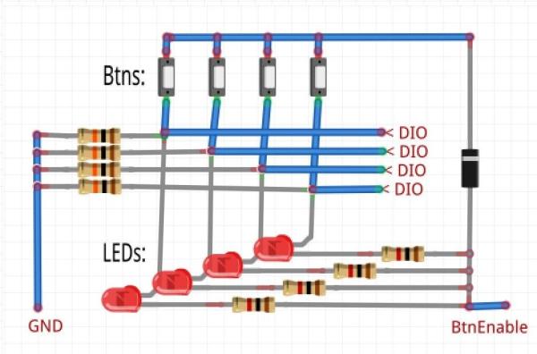
Notice there is a 10K pull-down on each I/O line to ensure a logic ‘Low’ when used for digital input and the button is open.
In 5 DIO line operation …
When using a ‘BtnEnb’ the line go directly to all the LEDs sinking current from them when it is low; a pull-up voltage goes to all of the buttons through a diode when the line is high.
In 4 DIO line operation …
The LEDs negative side goes to a ground (GND) connection; while the group of buttons is permanently connect to +V through a single1K resister.
When not using a BtnEnb control line but still multiplexing between Buttons and LEDs, there will be a momentary illumination of the corresponding LED when the buttons are scanned and the button is pressed. If the LED is not already lit you will see a low level dimming of it. To witness this run the second test ‘timer()’ and press btn 2 and or 3. This is a visual phenomena only and has no functional effect. And if this is not an issue for you, you have freed up another I/O line.
Apparently when you switch a line’s mode to output then back to input it losses it’s previous output state. This is true at least with the AVR 8bit MCUs. This is why in the above code the output states are saved before reading the buttons and then established. Additionally I found that PWM use of the LEDs does not work in this shared I/O configuration. So I wrote a display update routine (called at approximately one per millisecond) which, in addition to three easy to manage levels of dim, regular and bright, supports software driven PMW levels of 0 to 100% in 10% steps. One advantage here is that the digital I/O lines used do not need to have hardware PWM support.
Software PWM SAMPLE CODE executed regularly (e.g. 1/msec) :
// support for 10% PWM type gradations of lighting LEDs
    ledTime++;
    for (int i=1; i<=nleds; i++) {  // provide for lighting of 0-10 levels
      digitalWrite(led[i], (levelOn[i]>(ledTime%10)));
    }
If you are not using the fifth control line ‘BtnEnb’ Set it = 0.
If you want to use any of the sketch with the buttons and LEDs on independent I/O lines comment out the line:
#define DIO_SHARING
BTW, while considering sharing I/O lines, If you put a passive piezo buzzer on the same I/O line as the on-board LED, an alternating signal will result in audio while a DC (fixed level) will turn the LED either On of Off (it will flicker during audio).
In development I tested with a few differently devised 4×4 test fixtures and MCU dev boards, as well as on older project devices that did Not utilize share DIO and had various numbers of LEDs. So in the sketches, near the top, you will notice there are a few commented out blocks of hardware mapping configurations, that I would switch in and out. These should server in guiding you in formulating whats appropriate for your use case.
Example Hardware Configuration code:
/********* Standard Fixture Active HIGH conf for UNO/Nano/miniPro **********
    const int button[] = {2, 3, 4, 5}; //The four button input pins
    #define PRESSED_STATE 1
    #define DIO_SHARING
    #define BTN_ENB 6
    const int nleds=4;
    const int lites[]  = {2, 3, 4, 5};     //the LED pins
    #define ON_STATE 1
/********** for testing with My old little Black-Box Project  **************/
    const int button[] = {19, 18, 17, 16}; //The four button input pins
    #define PRESSED_STATE 0
    //NO:  DIO_SHARING
    #define BTN_ENB 0
    const int nleds=8;
    #define ON_STATE 0
    const int lites[] = {2, 3, 4, 5, 6, 7, 8, 9};     //the LED pins
/*****/
Note: The block who’s header ends with a “/” will be the active block.
Step 4: Software, the 4×4 Test Suite
The main MCU test sketch-program is MCU_Test_4x4.ino (found within the attached zip file along with other sketches). The following is an overview of its operations. For full details refer to the appropriate .odt file user manual.
During initialization ‘setup’, this is what transpires:
- configure I/O lines modes and levels
- Light the 4 LEDs 1 after the other, 1 second intervals, along with four different audio alerts (the third will only give a click if a passive buzzer (or speaker) is used and ACTIVE_BUZZER is not set to false)
- A One millisecond Interrupt Service Routine is setup and started, which will result in the 4 LEDs being turned OFF.
- An analog read of a reference voltage is made, and calculated Vcc is “SerialPrinted” (115,000 baud), as well as the number of 0.1 volts over 3.0 is counted out on the Led display.
- Led1 starts flashing at 1/2 Hz (1 second on, 1 second off), and the first button press is awaited before proceeding to the menu.
If there are any wiring or configuration problems they will be reflected in the above process, which will accordingly fail and/or falter.
Four test functionalities is then select-able.
1: BtnReporting() Verifies each button and Led wiring assignment and operation. Including button combinations and Serial print outs.
2: Scales()For checking standard Light and Audio levels (& thus delay timing). Exercises two Light and sound scales plus a sets of audio/visual effects.
3: Timer() Exercises millis() timing. Optionally tests ISR millisecond timing accuracy.
4: PerfTest() MicroControlerUnit “practical” Performance Test. Counts how many times a second a set of Analog & Digital I/O with Floating Pt. & Integer math plus general logic can be done. Also exercises EEPROM storage.
( “MCU marks”, for an AtMega328 16MHz: MPU Marks = 5100 )
Source: Test Any MCU Using Only 4 I/O Lines