Summary of Temperature Sensing with Arduino
This article details a CanSat Primary Mission project to measure temperature using an Arduino Uno R3 and an NTCLE101E3 thermistor. The system employs a voltage divider circuit connected to the A0 pin to determine resistance, which is then converted to temperature using the Steinhart-Hart equation. While the setup successfully detects temperature changes, the author notes initial accuracy issues requiring further investigation.
Parts used in the CanSat Temperature Sensing Project:
- Arduino Uno R3 micro-controller
- Resistors (specifically 10kΩ fixed resistor)
- NTCLE101E3 NTC Thermistor
As part of the CanSat Primary Mission, we need to measure temperature. For this our starter kit has given us an Arduino Uno R3 micro-controller, as well as some resistors and an NTCLE101E3 NTC Thermistor.
The thermistor is a special kind of resistor that changes its resistance with temperature. In our case we have an NTC, or Negative Thermal Coefficient thermistor. This is just engineering speak for “the resistance falls as the temperature rises”. Taking a look at the data sheet for the thermistor will show the resistance versus temperature curve.
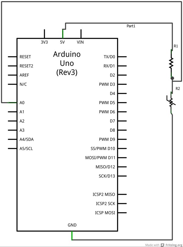
 The first step is to set up a circuit as shown in the diagram. Here we are going to use the Arduino A0 pin to sense the voltage at a point between resistor R1 and the thermistor R2. If you are familiar with electronics, you’ll recognise this as a voltage divider.
The voltage sensed at the Arduino A0 pin, will be given by:
A0 = Vin * Rt/(R1+Rt)
Where R1 is the fixed resistance resistor. We have chosen this to be 10kΩ, as our thermistor has a nominal value of 10kΩ at 25 degrees Celsius. Rt is the resistance of our thermistor.
So far so good, we can measure the voltage, and based on it, calculate the resistance of the thermistor. This is good, but how do we get to temperature?
Luckily, we have Professor John S. Steinhart and Dr. Stanley R. Hart to thank. In 1968 they published a model for the resistance of thermistors at different temperatures. It is known as the Steinhart-Hart equation, and is given by:
1/T = A + B ln(R) + C(ln(R))^3
Where:
T is the temperature in kelvin,
R is the resistance (in ohms) at temperature T
and A, B and C are the Steinhart-Hart coefficients, which will vary depending on the type and model of thermistor.
Thermistor manufacturers will often publish the Steinhart-Hart coefficients as part of product documentation, but unluckily for us, they have not. In this case we can derive them if we have at least 3 measurements of resistance and temperature. We have reference resistances given in the data sheet for known temperatures, so for a quick fix we can use these to derive the coefficients.
Knowing this, we can write our Arduino code to measure the voltage at A0, use the voltage to calculate the thermistor resistance, then use this resistance to calculate the temperature.
/** Program to read the temperature from the NTC thermistor.*/// -- setup() is executed once when sketch is downloaded or Arduino is resetvoid setup() { Serial.begin(9600); // open serial port and set data rate to 9600 bps Serial.println("Thermistor temperature measurement:"); Serial.println("\n Vo Rt T (C)");}// -- loop() is repeated indefinitelyvoid loop() { float temp = readTemp(A0); delay(1000);}/** Reads the temperature of a thermister, at the given pin.* Return the temperature as Kelvin*/float readTemp(int pin){ int Vo; // Integer value of voltage reading float R = 9830.0; // Fixed resistance in the voltage divider /* * Steinhart-Hart Equation coefficients. * Calculated from datasheet reference temps/resistances. */ float c1 = 1.3084634E-03; float c2 = 2.344772E-04; float c3 = 1.04177209450756E-07; float logRt,Rt,T; Vo = 1023 - analogRead(pin); // Read thermister voltage Rt = R*( 1023.0 / (float)Vo - 1.0 ); // Calculate thermister resistance logRt = log(Rt); // Apply Steinhart-Hart equation. T = ( 1.0 / (c1 + c2*logRt + c3*logRt*logRt*logRt ) ); Serial.print(" "); Serial.print(Vo); Serial.print(" "); Serial.print(Rt); Serial.print(" "); Serial.println(kelvinToCelcius(T)); return T;}float kelvinToCelcius(float temp){ return temp - 273.15;} |
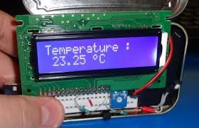
 Testing shows the reported temperature change when we touch the thermistor, for example, so our solution is beginning to work. On the down side though, the temperature values aren’t very accurate, and seem to be a few degrees off when the temperature changes from room temperature (around 20 degrees C). I’ll have to do some work to investigate the accuracy I can expect of the range of temperatures capable of being detected by this hardware configuration.
For more detail: Temperature Sensing with Arduino
- What type of thermistor is used in this project?
The project uses an NTCLE101E3 NTC Thermistor, where resistance falls as temperature rises. - How is the voltage measured in the circuit?
The Arduino A0 pin senses the voltage at a point between the fixed resistor R1 and the thermistor R2 in a voltage divider configuration. - Which equation is used to calculate temperature from resistance?
The Steinhart-Hart equation is used: 1/T = A + B ln(R) + C(ln(R))^3. - Where are the Steinhart-Hart coefficients found?
The article states that manufacturers often publish these, but for this specific thermistor, they were derived using reference values from the data sheet. - What is the fixed resistance value chosen for R1?
A 10kΩ resistor was chosen because the thermistor has a nominal value of 10kΩ at 25 degrees Celsius. - Does the code return temperature in Celsius or Kelvin?
The readTemp function returns the temperature in Kelvin before it is converted to Celsius for printing. - How accurate are the temperature readings reported in the text?
The testing showed the values are not very accurate and seem to be a few degrees off compared to room temperature. - Can the Arduino detect temperature changes when touched?
Yes, testing shows the reported temperature changes when the thermistor is touched.