Summary of Temperature Controlled Vaccine & Insulin Cooler
This article details a DIY, open-source vaccine and insulin cooler designed for resource-limited regions. It solves the challenge of maintaining 2-8°C temperatures without grid power by combining dry ice with an Arduino-based PID controller. The system separates the freezing dry ice from cargo using a fan to circulate chilled air, ensuring precise temperature regulation while remaining mobile and energy-efficient.
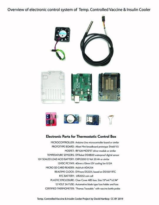
Parts used in the Temperature Controlled Vaccine & Insulin Cooler:
- Closed-cell foam insulation sheets
- Construction adhesive and silicone caulk
- Aluminum furnace tape and high-adhesion utility tape
- Double reflective air roll furnace insulation
- PVC pipes (1.5 inch inner diameter)
- Arduino Uno R3 microcontroller board
- Stackable prototype board or breadboard shield
- MOSFET driver module IRF520
- Digital temperature sensor DS18B20
- Brushless 12V PC cooling fan
- Rechargeable sealed lead acid battery (12V 20AH)
- Micro SD card reader and Realtime clock module
- Vaccine thermometer with probe
- Flower-stem bottles for liquid buffering
- Various electronic components including resistors, wires, fuses, and connectors
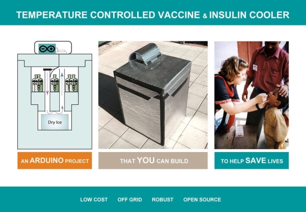
Keeping cool saves lives
In the developing world, vaccines are the front line of defense against dangerous illnesses such as Ebola, Influenza, Cholera, Tuberculosis and Dengue to name a few. Transporting vaccines and other life-saving materials such as insulin and blood require careful temperature control.
First-world logistics tend to break down when supplies are transported into regions with limited resources. Many rural medical clinics lack the funding or the energy for ordinary refrigeration systems.
Insulin, human blood, and many common vaccines must be kept in the temperature range of 2-8 ˚C. In the field, this can be difficult to maintain because electric refrigeration requires too much power, and passive ice coolers lack thermostat control.
Arduino to the rescue
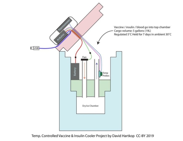
This project combines the compact cooling power of dry-ice (solid carbon dioxide) with the precision of digital temperature control. When used by itself, dry ice too cold to transport vaccine, insulin or blood because it can easily lead to freezing. This project’s cooler design solves the problem of freezing by placing the dry ice in a separate chamber below the cargo cooler. A brushless PC fan is used to circulate small doses of super-chilled air through the cargo section as needed. This fan is controlled by a robust Arduino microcontroller, running a precision (PID) temperature control loop. Because the Arduino system runs on very little electrical power, this system can be mobile like an ice chest, but temperature-regulated like a plug-in refrigerator.
Who is this project for?
It is my hope that, by making this system free and open source, it will inspire humanitarian engineers and aid workers to look for ways to produce useful technologies near to the point of need.
This project is designed to be built by students, engineers, and aid workers in or near areas facing humanitarian challenges. The materials, parts, and supplies are generally available in most of the world’s cities in even the poorest countries. By making the plans available for free through Instructables, we are providing technology with flexibility in terms of cost and scalability. The decentralized manufacture of these arduino-ice coolers may be in important option with the potential to save lives.
Finished cooler specifications:
- Cargo volume: maximum 6.6 gallons (25L), recommended 5 gallons (19L) with buffer bottles.
- Maximum cargo volume dimensions: =~14 in x 14 in x 8 in (35.6 cm x 35.6 x 20.3 cm)
- Cooling Capacity: Maintains 5°C for 10-7 days in 20-30°C ambient environment respectively.
- Power source: dry ice and flooded 12 volt marine cell battery.
- Over all dimensions: 24in x 24 in x 32 in tall (61 cm x 61 cm x 66.6 cm tall)
- Over all weight: 33.3 lb (15.1 Kg) empty with no ice / 63 lb (28.6kg) with full ice and cargo.
- Temperature regulation: PID control holds 5°C +-0.5°C
- Materials: construction grade closed-cell foam and construction adhesives with IR reflective insulation jacketing.
Step 1: Setup for the Project
Workspace:
- This project requires some cutting and gluing of styrene foam insulation. This can produce some dust, especially if you opt to use a saw rather than a knife. Be sure to use a dust mask. Also, it is very useful to have a shop-vac on hand to clean up the dust as you go.
- Construction adhesive can release irritating fumes when drying. Be sure to complete the gluing and caulking steps in a well ventilated area.
- Assembling the arduino add-on components requires the use of a soldering iron. Use lead-free solder when possible, and be sure to work in a well lighted, well ventilated space.
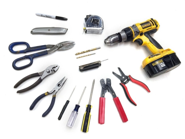
All tools:
- Circular saw or scoring knife
- Cordless drill with 1.75 inch hole saw bit
- Soldering iron & solder
- Lighter or heat gun
- 4-foot straight edge
- Sharpie marker
- Ratchet straps
- Tape measure
- Caulking tube dispenser
- Wire cutter/Strippers
- Screwdrivers large and small phillips & regular
All supplies:
Electronics Supplies
- Shrink Tubing 1/8 and 1/4 inch
- Circuit board pin headers (female sockets and male pins)
- ABS plastic electrical box with clear cover, size 7.9″x4.7″x2.94″(200mmx120mmx75mm)
- Rechargable sealed lead acid battery, 12V 20AH. NPP HR1280W or similar.
- Arduino Uno R3 microcontroller board or similar
- Arduino stackable prototype board: Alloet mini breadboard prototype shield V.5 or similar.
- MOSFET driver module IRF520 or similar
- Digital temperature sensor DFRobot DS18B20 in waterproof cable package
- Brushless 12V PC cooling fan: 40mm x 10mm 12V 0.12A
- Micro SD card reader: Adafruit ADA254
- Realtime clock: DIYmore DS3231, based on DS1307 RTC
- Battery for realtime clock: LIR2032 coin cell)
- 4.7 K-ohm resistor
- 26 gauge stranded hook-up wire spools (Red, Black, Yellow)
- Length of 2-conductor wire (3 ft or 1m) 12 gauge stranded (battery hook up wire)
- Automotive blade fuse holder and 3 amp blade fuse (for use with battery)
- USB printer cable (type a male to b male)
- Wire nut (12 gauge)
Tapes & Adhesives Supplies
- High-adhesion utility tape 2 inch wide x 50 ft roll (Gorilla Tape or similar)
- Silicone caulk, one tube
- Construction adhesive, 2 tubes. (Liquid Nails or similar)
- Aluminum furnace tape, 2 inch wide x 50 ft roll.
- Self adhesive hook-and-loop strips (1 inch wide x 12 inches total needed)
Construction Materials Supplies
- 2 x 4 foot x 8 foot x 2 inch thick (1200 mm x 2400 mm x 150 mm ) foam insulation sheets
- 2 ft x 25 ft roll of double reflective air roll furnace insulation, silver bubble.
- 2 x short PVC Pipes, 1 1/2 inch inner diameter x Sch 40. cut to 13 inch lengths.
Specialty Supplies
- Vaccine thermometer:’Thomas Traceable Refrigerator/Freezer Plus Thermometer with Vaccine Bottle Probe’ and traceable calibration certificate or similar.
- 2 x Flower-stem bottles for liquid-buffering the DS18B20 waterproof temperature probes.
Step 2: Cut Out the Foam Parts
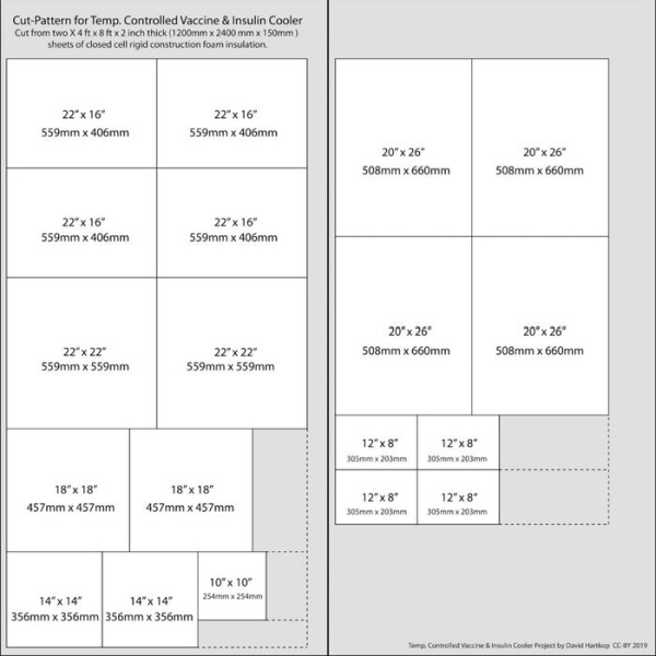
Print out the cut-pattern, which shows a number of rectangles to cut from two 4 ft x 8 ft x 2 in (1200 mm x 2400 mm x 150 mm ) sheets of rigid closed cell foam insulation.
Use a straight edge and marker to carefully draw the lines for cutting the foam sheets. The foam may be cut by scoring it with a utility knife, but it is easiest to use a circular saw to do the job. Cutting foam with a saw, however, produces dust that should not be inhaled. Important precautions should be followed:
- Wear a dust mask.
- Use a vacuum hose attached to the saw for dust collection.
- Do the cutting outside if possible.
Step 3: Assemble the Cooler From Foam Sheets
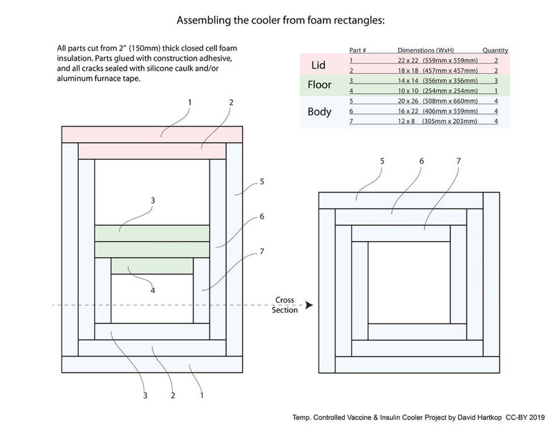
The included slides detail how to assemble the complete cooler from sheets of foam and silver bubble wrap insulation. It is important to let the construction adhesive dry between a few different steps, so you should plan to spend 3 or so days to complete all of these steps.
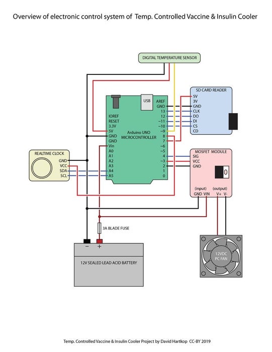
Step 4: Assemble the Controller System
The following images show how to assemble the electronics components onto prototype board to create the temperature control system for the cooler. The last image included is a full system schematic for your reference.
Step 5: Software Setup and Testing
First try this setup sketch
The setup sketch does two things. First, it lets you set the time and date in the Real Time Clock (RTC). Second, it tests all of the cooler controller’s peripheral components and gives you a little report through the serial monitor.
Download the most current setup sketch here: CoolerSetupSketch from GitHub
Open the sketch in the Arduino IDE. Scroll down to the block of code commented as “Set the Time and Date Here.” Fill in the current time and date. Now, double check that the following peripherals are setup and ready before you upload the sketch (see included electrical schematic image):
- Temperature Probe plugged into one of the 3 pin header sockets
- Micro SD card inserted into the reader module
- Coin cell battery inserted into the real time clock (RTC) module
- Hook up wires connected to the PC fan
- Fuse in the fuse holder of the battery wire.
- Arduino connected to the battery (being SURE it is not wired backward! + to VIN, – to GND!)
In the Arduino IDE, Select Arduino UNO from the list of boards, and upload. Once the upload is done, from the dropdown menu at the top, select Tools / Serial Monitor. This should display a little system report. Ideally, it should read something like this:
<p>Cooler Setup Sketch - version 190504<br>START OF SYSTEM TEST ----------------------
TESTING REAL-TIME CLOCK: time[20:38] date[1/6/2019]
TESTING TEMP. SENSOR: 22.25 C
TESTING SD CARD:
init done
Writing to dataLog.txt...dataLog.txt:
If you can read this, then your SD Card is working!
TESTING FAN: Is the fan pulsing on and off?
END OF SYSTEM TEST ----------------------</p>
Trouble-shoot the system
Usually for me, things never go quite as planned. Some system probably didn’t work right. The setup sketch will hopefully provide a clue – the clock? The SD card? The most common problems with any microcontroller project usually have to do with one of these:
- you forgot to put a fuse into the battery wire, so no power
- you forgot to put a micro SD card in the reader, so the system is hanging
- you forgot to put a battery in the real time clock (RTC) so the system is hanging
- connected sensors are loose, disconnected, or connected in reverse
- wires for components are left disconnected, or connected to the wrong Arduino pin(s)
- the wrong component is plugged into the wrong pins or is wired backward
- there is a wire improperly attached that is shorting everything out
Install the controller sketch
Once you have had a successful test with the CoolerSetupSketch, it’s time to install the full controller sketch.
Download the most current controller sketch here:CoolerControllerSketch
Connect the Arduino to your computer with a USB cable and upload the sketch with the Arduino IDE. You are now ready to physically install the whole system into the body of the cooler.
Step 6: Install the Arduino System
The following steps can be treated as a checklist or installing all the electronics. For the following steps, refer to the included photos of the finished project. Pictures help!
- Attach a pair of fan wires to the Arduino UNO module.
- Attach a pair of 12-volt power wires to the Arduino UNO module.
- Attach the DS18B20 temperature sensors to the Arduino UNO module. Just plug the sensor into one of the 3-pin socket(s) we installed in the prototype board. Pay attention to the wire colors, red goes to positive, black to negative, and yellow or white goes to the 3rd data pin.
- Plug a USB printer cable into the Arduino’s USB connector.
- Use the 1.75″ hole saw to drill a large round hole in the bottom of the electronics box.
- Attach the Arduino UNO module to the bottom of the electronics box using self-adhesive hook-and-loop fastener strips.
- Attach the calibrated vaccine thermometer to the underside of the clear lid of the box with hook-and-loop fastener strips. Connect its small liquid-buffered bottle probe wire.
- Pass the following wires out of the box through the round hole in the bottom:
- 12-volt power wires (12-18 gauge stranded copper 2 conductor speaker wire)
- Arduino temperatures sensor(s) (DS18B20 with male 3 pin header connector on each)
- USB printer cable (Type A Male to Type B Male)
- Vaccine Thermometer probe (Included with calibrated thermometer)
- Fan wires (twisted pair of stranded 26 gauge hook-up wire)
- Open the lid of the cooler and use a knife or a drill to bore a 3/4 inch (2 cm) hole through the lid near one of the back corners. (See included pictures) Poke up through the mylar bubble wrap covering.
- Feed all but the USB wire from the control box down through the lid from the top. Place the box onto the lid with the USB cable hanging out so it can be accessed later. Secure the box with high-adhesion tape.
- Screw the clear lid of the electronics box onto the box.
- Create a flap of additional silver mylar bubble wrap insulation to cover the box and protect it from direct sunlight. (See included pictures.)
- Inside the cooler, place the 12 volt 20AH battery near the back of the compartment. The battery will remain inside the chamber alongside the cargo. It will work well even at 5˚C, and will serve as some thermal buffering, similar to a water bottle.
- Attach both of the temperature probes (the thermometer’s bottle probe and the Arduino probe) to the base of the center pipe using high-adhesive tape.
- Inside the cooler, use aluminum tape to attach the fan so that it blows down into the corner pipe. Connect its wires to the wires from the controller. The fan blows down the corner pipe, and super chilled will fountain up into the cargo chamber from the center pipe.
Step 7: Cooler Startup and Operation
- Format the Micro SD card – the temperature will be logged to this chip
- Recharge the 12 volt battery
- Purchase a 25 lb (11.34kg) block of dry ice, cut to dimensions 8 in x 8 in x 5 in (20 cm x 20 cm x 13 cm).
- Install the ice block by first placing the block flat on towel on a table. Slide the silver Mylar liner over the block so that only the bottom surface is exposed. Now lift the entire block, flip over so the bare ice faces upward, and slide the whole block into the dry ice chamber below the cooler floor.
- Replace the cooler floor. Use aluminum tape to tape around the outer edge of the floor.
- Place the 12 volt battery into the body of the cooler. You may wish to secure it to the cooler wall with strips of high adhesive tape.
- Connect the controller power wire to the battery.
- Check to see that the temperatures probes are securely taped.
- Load water bottles into the cargo compartment to fill nearly all of the space. These will buffer the temperature.
- Set the cooler somewhere out of direct sunlight and allow 3-5 hours for the temperature to stabilize at 5C.
- Once the temperatures has stabilized, temperature sensitive items may be added by removing water bottles and filling that volume with cargo.
- This cooler with a fresh charge of ice and power will sustain a controlled 5C for up to 10 days without any additional power or ice. The performance is better if the cooler is kept out of direct sunlight. The cooler can be moved and is resistant to shock in most respects; it should, however, be kept upright. If tipped over, simply stand it back up, no harm done.
- The remaining electrical power in the battery can be measured directly with a small volt meter. The system requires a minimum of 9 volts to function properly.
- The remaining ice can be measured directly with a metal tape measure by measuring down the center pipe-hole up to the top edge of the PVC pipe. See the attached table for measurements to remaining ice-weight.
- Temperature logging data can be downloaded by attaching the USB wire to a laptop running the Arduino IDE. Connect, and open the Serial Monitor. The Arduino will automatically restart and read the full log out through the serial monitor. The cooler will continue to function without interruption.
- The data can be downloaded from the enclosed MicroSD Card, but the system must be powered-down before pulling out the tiny chip!
Step 8: Notes and Data
This cooler was designed to be a decent balance of size, weight, capacity, and cooling-time. The exact dimensions described in the plans can be considered a default starting point. They can be modified to better suit your needs. If, for instance, you require a longer cooling time, the dry-ice chamber can be constructed with a taller volume for more ice. Likewise, the cargo chamber can be built wider or taller. Care should be taken to experimentally prove-out any design changes you make, however. Small changes can have a large impact on overall system performance.
The attached documents include experimental data recorded through development of the cooler. Also included is a comprehensive parts list for purchasing all of the supplies. Additionally, I have attached working versions of the Arduino sketches, though the GitHub downloads above will most likely be more current.
Step 9: Links to Online Resources
A PDF version of this instruction book can be downloaded in full, see included file for this section.
Visit the GitHub repository for this project:
https://github.com/IdeaPropulsionSystems/VaccineCoolerProject
Source: Temperature Controlled Vaccine & Insulin Cooler
- How does this project prevent vaccines from freezing?
The design places dry ice in a separate chamber below the cargo section and uses a fan to circulate controlled amounts of super-chilled air. - Can this cooler operate without access to electrical grids?
Yes, it runs on a flooded 12 volt marine cell battery powered by dry ice, making it mobile like an ice chest. - What is the recommended cargo volume for this cooler?
The maximum volume is 6.6 gallons, but 5 gallons with buffer bottles is recommended. - How long can the cooler maintain a temperature of 5°C?
It maintains 5°C for up to 10 days in an ambient environment of 20-30°C. - Does the system require manual temperature adjustments?
No, an Arduino microcontroller runs a precision PID temperature control loop to hold 5°C plus or minus 0.5 degrees. - What tools are needed to cut the foam insulation?
A circular saw or scoring knife is required, along with safety gear like a dust mask. - How is the temperature data recorded during transport?
The system logs temperature data to a Micro SD card which can be downloaded via USB connection. - What happens if the cooler is tipped over?
The cooler is resistant to shock; if tipped, simply stand it back upright with no harm done.