Summary of Temp & Humidity Sensor With LCD Disp & LED Indicator
Summary (under 100 words): This project uses a DHT11 temperature and humidity sensor with an Arduino UNO to display readings on a 16x2 LCD and drive a 3-LED indicator for temperature ranges (cold, hot, extreme). The guide covers required parts, wiring details (pin-by-pin), library installation, Arduino sketch, and behavior: green LED for 35°C. The sensor updates about once per second and the wiring diagram and images are provided to help assembly.
Parts used in the Temp & Humidity Sensor With LCD Disp & LED Indicator:
- Breadboard
- 16 X 2 LCD Display
- Jumper wires
- Arduino UNO Board
- Arduino IDE installed on your computer
- 3 LEDs (three different colors: green, yellow, red)
- Mini Breadboard (optional)
- DHT11 Temperature & Humidity Sensor
- Potentiometer (optional for LCD contrast/brightness)
In this instructable, I have used the DHT11 Temperature & Humidity sensor & Arduino UNO to display the current temperature & humidity readings into a 16 x 2 LCD Display. Alongside, I have also created a 3-LED setup which indicates 3 sets of temperature readings (cold, hot, extreme).
The DHT11 is a digital sensor that lets you easily get relative humidity and temperature readings in your projects. Because of their low cost and small size, DHT11 sensors are perfect for lots of different DIY electronics projects. Some projects where the DHT11 would be useful include remote weather stations, home environment control systems, and agricultural/garden monitoring systems.
DHT11 Technical Specifications :
- Humidity Range: 20-90% RH
- Humidity Accuracy: ±5% RH
- Temperature Range: 0-50 °C
- Temperature Accuracy: ±2% °C
- Operating Voltage: 3V to 5.5V
Next, I will be describing step-wise with relevant images, how to hook up the 16 x 2 LCD Display to the Arduino, the relative connections of the DHT11 sensor & the 3-LED setup.
Step 1: Stuffs You Will Need for This Project
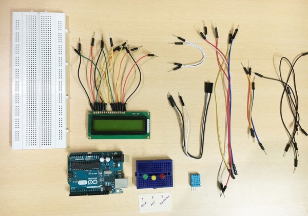
- Breadboard
- 16 X 2 LCD Display
- Jumper wires
- Arduino UNO Board & Arduino IDE installed on your computer
- 3-LEDs (of 3 different colors)
- Mini Breadboard (not necessary)
- DHT11 Temp & Humidity Sensor
That’s all you need to get started . . .
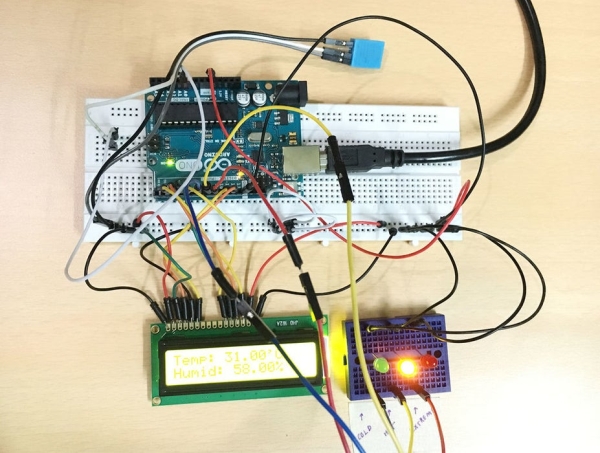
Step 2: Setting Up the Connections With the Arduino
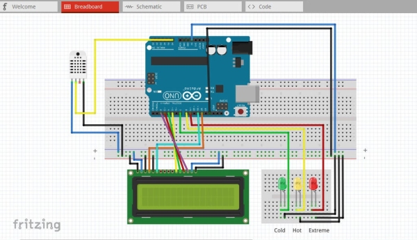
The connection part is the most important part of the whole project. Make sure you follow the directions properly or else you might end up destroying the sensor directly. The image above (and in Step 3 below) shows the connections of the setup in the breadboard in a clean way. Deep-Blue wires correspond to the 5V connection & Black wires correspond to the Ground connection
1. The 16 x 2 LCD Display consists of 16 pins which are labelled with different names, written on the back of the display module. Make sure you follow the pin numbers correctly.
2. To know the pins of the DHT11 sensor, refer to the wiring diagram above.
In case, the wiring diagram feels a bit too complex, here is the connection setup list pin wise :
- Arduino GND to breadboard Negative power rail (All black wires goes to this rail)
- Arduino 5V to breadboard Positive power rail (All deep-blue wires goes to this rail)
- DHT11 Positive pin to breadboard positive power rail
- DHT11 Negative pin to breadboard negative power rail
- DHT11 Signal pin to Arduino Analog A0 (this feeds data from DHT11 to Arduino)
- LCD 1 to breadboard Negative power rail
- LCD 2 to breadboard Positive power rail
- LCD 3 to breadboard Negative power rail (if you connect this to a potentiometer, this helps to change the LCD brightness)
- LCD 4 to Arduino Digital Pin 12 (LCD character coordinates)
- LCD 5 to breadboard Negative power rail
- LCD 6 to Arduino Digital Pin 11 (LCD initiate command)
- LCD 11 to Arduino Digital Pin 5
- LCD 12 to Arduino Digital Pin 4
- LCD 13 to Arduino Digital Pin 3
- LCD 14 to Arduino Digital Pin 2
- LCD 15 to breadboard Positive power rail
- LCD 16 to breadboard Negative power rail
- Cold/Green LED Positive Pin to Arduino Digital Pin 7 (negative pin to breadboard negative rail)
- Hot/Yellow LED Positive Pin to Arduino Digital Pin 8 (negative pin to breadboard negative rail)
- Extreme/Red LED Positive Pin to Arduino Digital Pin 9 (negative pin to breadboard negative rail)
If you have made the connections properly, you are almost half-way through the project since the rest steps are easy to follow with.
Step 3: What Your Setup Will Probably Look Like
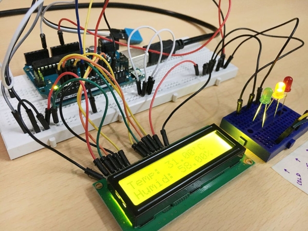
I have uploaded few images above to see how each connections look like. Since this is a complex circuit, I have tried my best to keep wiring connections as simple as possible. Hope this might help you at some stage.
Next before moving on the coding part, what we need are two Arduino Libraries for our LCD Display & DHT11 sensors to work properly. I have had a tough time finding the correct library for the DHT11 sensor because most of them were outdated. However, the LCD Display library is inbuilt within the Arduino IDE.
Nevertheless, I have attached the two library files. If you don’t know how to install an Arduino Library inside the IDE, it’s quite easy : Open Arduino IDE –> Sketch –> Include Library –> Add Library and select the .zip files.
Step 4: The Sketch (a.k.a Arduino Code)
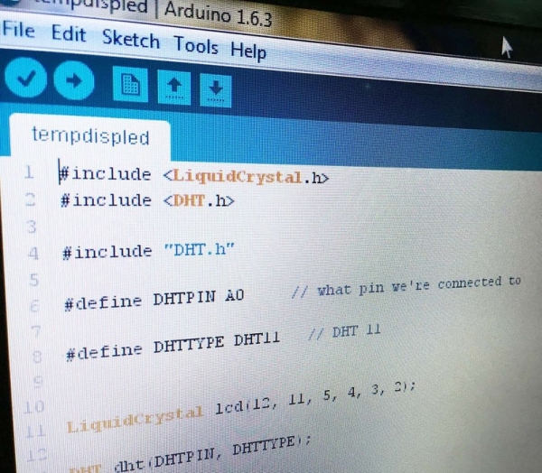
This is the code, you will have to compile & upload to your Arduino UNO board. If you have made all the connections & library installation exactly as described, the code compilation should probably produce no errors.
#include <LiquidCrystal.h>

#include <DHT.h>#include "DHT.h"#define DHTPIN A0     // what pin we're connected to#define DHTTYPE DHT11   // we are using the DHT11 sensorLiquidCrystal lcd(12, 11, 5, 4, 3, 2);DHT dht(DHTPIN, DHTTYPE);void setup()
{
  Serial.begin(9600);
  for (int DigitalPin = 7; DigitalPin <= 9; DigitalPin++)
 {
  pinMode(DigitalPin, OUTPUT);
 }
  lcd.begin(16,2);  //16 by 2 character display

dht.begin();
}
Step 5: Describing the Setup Overall
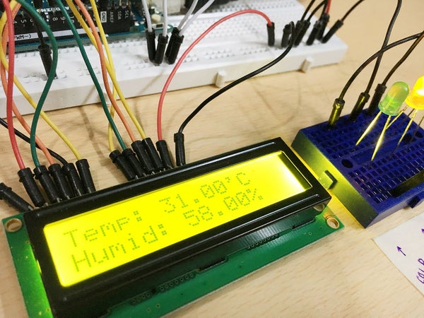
After the code/sketch has been successfully compiled & uploaded to the Arduino, you will see the current temperature & humidity of your surroundings. The sensor basically refreshes every 1 second to update you with the accurate temperature. Alongside this, you will notice any one of the LED being lit, depending upon your surroundings.
3-LED setup has been initiated with the following :
- If the temperature is below 22℃, the Cold LED will glow. (Green)
- If the temperature is between 22 – 35℃, the Hot LED will glow. (Yellow)
- If the temperature is above 35℃, the Extreme LED will glow. (Red)
One can obviously modify the readings in the code as per your choice.
I have uploaded two images above with the normal temperature of our area 31 ℃ (with the Yellow/Hot LED being lit). I then, put the sensor near an Ice cube to drop the temperature below 22℃ (to make the Green/Cold LED lit up).
You can see the video attached, where i have shown the temperature change from 19℃ to 24℃ and the corresponding change in LED indicators.
P.S : Sorry, I could not rise up to the temperature of 35℃ (to show the Red LED glow), but it will definitely work like the other two LEDs.
That’t it !
Thanks a lot for following this. Hope I can upload a few more projects soon.
Incase you face any queries, feel free to ask in the comments 🙂
Source: Temp & Humidity Sensor With LCD Disp & LED Indicator
- What does this project do?
It reads temperature and humidity from a DHT11, displays them on a 16x2 LCD, and lights one of three LEDs based on temperature ranges. - Which pins connect the DHT11 and LCD to the Arduino?
DHT11 signal to Analog A0; LCD pins to Digital 12,11,5,4,3,2 and power rails as listed in the connections. - How are the LEDs wired and which pins control them?
Cold/Green LED positive to Digital Pin 7, Hot/Yellow to Pin 8, Extreme/Red to Pin 9; negatives to breadboard ground rail. - What temperature ranges trigger each LED?
Cold (green) below 22°C, Hot (yellow) between 22 and 35°C, Extreme (red) above 35°C. - How often does the sensor update readings?
The sensor refreshes roughly every 1 second according to the article. - Which Arduino libraries are required?
The LiquidCrystal library (built into the IDE) and a DHT library (provided as a ZIP in the guide). - Can I change the temperature thresholds?
Yes, the article states one can modify the readings in the code as per choice. - What power rails should be used for sensor and LCD?
Arduino 5V to breadboard positive rail and Arduino GND to breadboard negative rail; DHT11 and LCD power pins go to these rails. - Is a potentiometer required for the LCD?
No, it is optional; connecting LCD pin 3 to a potentiometer helps change LCD brightness/contrast. - Will the red Extreme LED work even if not demonstrated?
Yes, the author states it will work like the other two LEDs though they did not reach 35°C to demonstrate it.