This instructable was created in fulfillment of the project requirement of the Makecourse at the University of South Florida (www.makecourse.com)
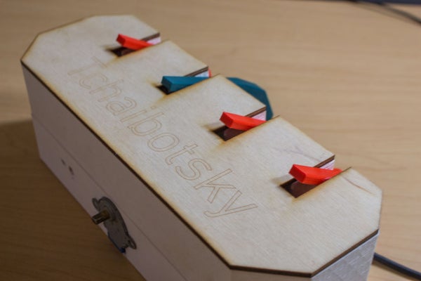
Tchaibotsky is an Arduino powered piano playing robot. The motivation was to build something that could accompany pianists, whether they’re missing an arm and can’t play the melody to a song, or they want to play a duet but have no friends. As of now, its limited in range to C major songs (no flats or sharps).
Materials:
- 3D printed top.
- 3D printed bottom.
- 8 3D printed fingers.
- 3D printed rod holder.
- 1/8″ inch plywood, about 11″x4″.
- 8 metal geared micro servos.
- Arduino Uno.
- Small breadboard.
- Jumper cables.
- 9V battery and adapter to power Arduino.
- External power supply (mobile battery bank).
- USB cable.
- 28byj-48 stepper motor.
- 2 1/8″ steel rods, 12″ long.
- 1 5/32″ tube, about 4″ long.
- 2 1/8″ tubes, about 10″ each.
Step 1: 3D Print the Parts
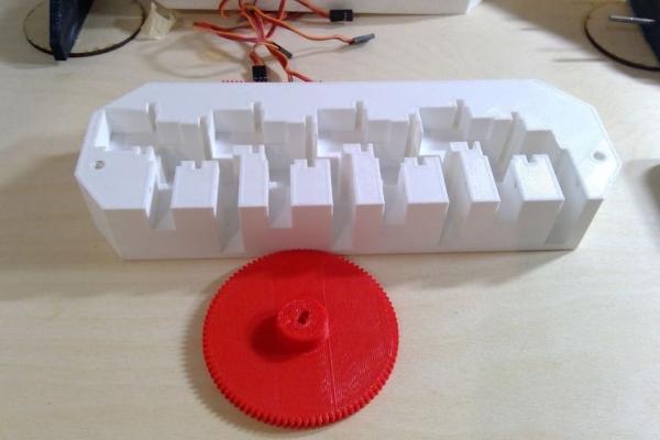
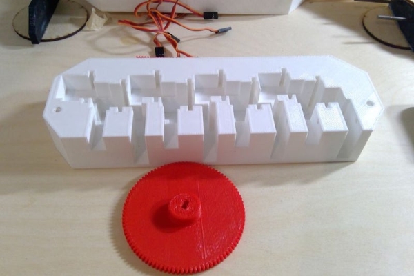
Most of the project is designed to be 3D printed. This includes the top and bottom housings, the 8 fingers, the rack and pinion, and the rod holders that support it.
There are two different versions of the fingers, finger 1 and finger 2. Finger 1 is the longer one and is designed to be fit with the servos on the top row. Finger 2 is shorter and goes with the servos on the bottom row.
The rack and pinion are a bit too fine now and are prone to slipping, so experiment and go with something a bit more coarse. Also limit the size of the pinion. The larger the pinion, the more torque the stepper needs to produce, and even with half stepper, it still stalls often now.
Print:
- 1xHand top
- 1xHand bottom
- 4xFinger 1
- 4xFinger 2
- 2xRod holder
- 1xRack
- 1xPinion
Step 2: Drill Holes in Housing.

Holes need to be drilled in the bottom of the housing to accommodate the IR receiver and the power cord.
Measure the diameter of your wires and drill into the backside to make a hole for the power coble to go through.
Drill a hole the size of the IR receiver in the front left of the bottom housing, like shown in the picture.
Step 3: Allign the Servos.
The servos should all be at the same angle. To accomplish this, set the servo position to 90 degrees using the Arduino and then attach the arm so that its parallel to the surface. Do this for all the servos before inserting them in the housing, making sure the arms are facing the right way.
Step 4: Insert the Servos.
The top housing has 8 holes designed to fit the servos. There are also holes to drop down the wires into the bottom portion.
Insert the 4 lower servos first and feed through the wires. Then insert the upper 4 servos and feed the wires through the same holes.
Make sure that all of the servo arms are roughly at the same angle once they’re inserted.
Step 5: Attach the Fingers.
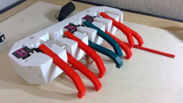
There are 8 fingers. 4 shorter ones and 4 longer ones. The longer ones go with the servos on the top row and the shorter ones go with the servos on the bottom.
Place the finger by inserting it into the slot and skewering it with the 1/8″ tube.
Trim off the excess tube and file flush.
Step 6: Attach the Power Supply.
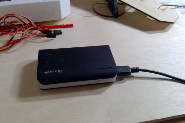
For this project I used an external power supply by means of a battery bank. I did this because it was rated at 5V and could supply up to 2A. Each servo takes about 200mA and the Arduino can’t provide enough current by itself to power all the servos.
Break off the power rail from a small breadboard and stick into the bottom on the bottom housing.
I stripped a USB wire and removed the data lines. A USB cable will have 4 wires inside: a red, black, green and white. The red and black are the only ones we need. Strip these. I soldered them into the connector of a 9V battery because the wires were fine strands that wouldn’t insert into the breadboard and I happened to have the 9V adapter laying around. I then put the positive and negative into the breadboard.
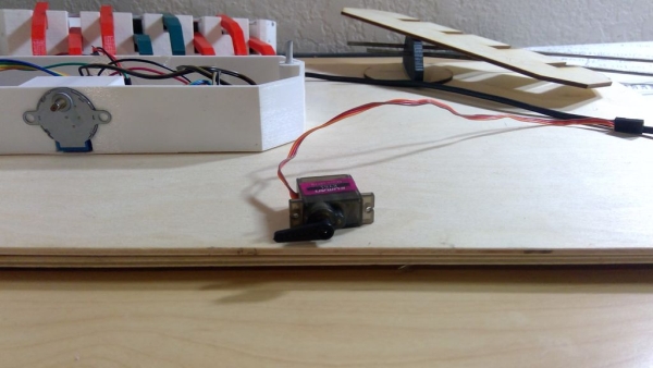
Step 7: Mount the Stepper Motor and Driver Board.
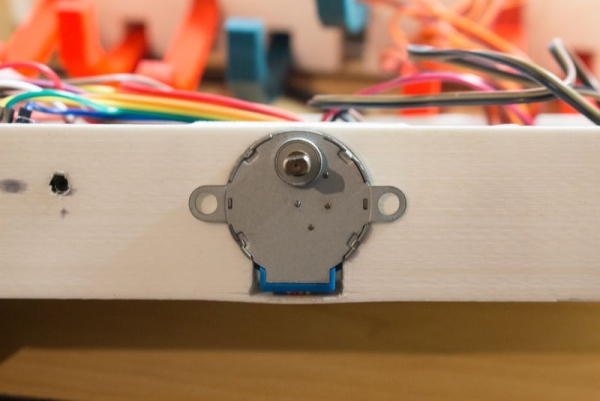
Insert the stepper motor into the bottom housing, carefully tucking the wires through the hole.
Hot glue the driver board wherever convenient.
Step 8: Attach the Wires.
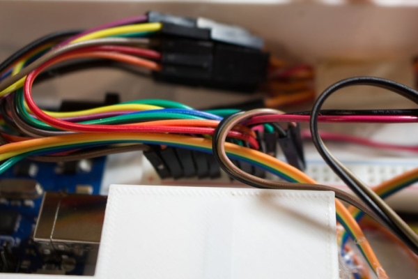
The 8 servo digital leads are attached to digital pins 2-9. It is vital that they are attached in the correct order. The left most servo (servo1), as seen in picture 4, attaches to pin 2. Servo2 attaches to pin 3 and so on. The servo’s positive and negative leads are attached to the breadboard. The 4 wires on the stepper controller board labeled IN 1 – IN 4 are attached to digital pins 10-13. The positive and negative wires from the stepper controller board are plugged into the breadboard. The IR receiver is connected to the 5V and ground pins on the Arduino and the data pin is connected to analog pin 1.
In the Fritzing diagram the power supply is represented by the two AA batteries. Don’t actually use two AA batteries. The stepper is also not attached in the diagram.
Source: Tchaibotsky (a Piano Playing Robot)