Summary of Synchronized 2-Axis Motion With Variable Speed (Arduino + LEDs + 28BYJ-48)
This tutorial shows how to synchronously move two 28BYJ-48 stepper motors with an Arduino using simple UI elements (LEDs, microswitches, potentiometer) and the AccelStepper library. It covers breadboard wiring, a first test without libraries, motion theory for synchronized timing and acceleration, installing AccelStepper, menu-driven UI behavior, final code overview, and testing/assembly tips to build a two-axis synchronous motion rig.
Parts used in the Synchronized 2-Axis Motion project:
- Arduino Nano (or Uno with 328P)
- Breadboard (830 holes)
- Jumper cables male-to-male (14)
- Jumper cables male-to-female (12)
- LEDs 5mm (2)
- Resistors 220 Ohm (2)
- Microswitches (2)
- Potentiometer 5 or 10 kOhm (1)
- 5V power supply (1)
- 28BYJ-48 stepper motors 5V (2)
- ULN2003 driver boards (2)
This tutorial shows how to move two stepper motors so they will synchronously arrive at defined destination point. There are many sophisticated solutions for doing this such as GRBL or Marlin. Using an Arduino, there are also dedicated “Multi Stepper” libraries that can support you. However, we will use a more basic approach here making it as easy as possible while adding a simple user interface using either three LEDs and some microswitches.
Supplies
- 1 Arduino Nano (or Uno, with 328P CPU)
- 1 Breadboard (830 Holes)
- 14 Jumper Cables (male-to-male, 10…20 cm)
- 12 Jumper Cables (male to-female, 10…20 cm)
- 2 LEDs (5mm, 20mA, around 2V)
- 2 Resistors (220 Ohm)
- 2 Microswitches
- 1 Potentionmeter (5 or 10 kOhm)
- 1 5V Power Supply
- 2 28BYJ-48 Stepper Motors (5V Version) + ULN 2003 Driver Boards
Step 1: Configure Your Breadboard
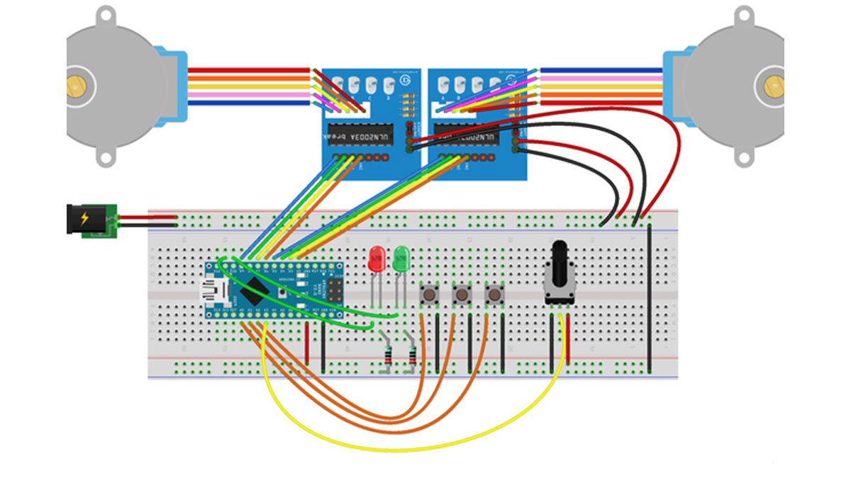
Set-up your breadboard as shown in the pictures above:
- Connect GND and 5V to the according rails of the breadboard.
- Pins D2 to D5 of the Arduino go to In1 to In4 of the first ULN2003 board.
- Pins D6 to D9 of the Arduino go to In1 to In4 of the second ULN2003 board.
- Pin D10 of the Arduino goes to the + leg (longer leg) of the first LED (red). Connect the shorter leg (-) to a 220 Ω resistor and the other end of this resistor to the ground rail.
- Connect D11 the same way to the second LED and its resistor.
- Connect the Arduino pins A0, A1, and A2 to the microswitches. Connect the other side of the microswitches to GND. We will not use any pull-up resistors to avoid short circuits here, because we use the pull-up that are already integrated in the Arduino.
- Connect the left leg of the potentiometer to ground, the right leg to 5V and the middle leg to A3 of the Arduino.
- The Arduino itself will be powered through the USB port during the first tests. Nevertheless, the motors should not be powered through the USB port. Hence, connect a separated power supply to plus/ground rails on the other side of the breadboard. Connect the + pin and – pins of each ULN2003 board to these plus/ground rails. As a last step, make a bridge between the both ground rails.
Step 2: A First Test
Now we can do a first test of our set-up and the included “user interface”.
Open the Arduino IDE and load the attached “Two_Steppers_-_First_Test.ino” file. It should compile without any additional libraries. Most of the code is pretty self-explanatory.
- The setup() method is only defining which pins will be used for input and out actions and open the serial connection to the PC.
- The loop() method now will continuously perform the following sequence:
- Read the value of the potentiometer from the analog input, scale for displaying values between 0 and 100%, read the buttons and print the status all input elements to the serial interface.
- Switch on one LED on and the other off.
- Using two for-loops, move each motor approximately a quarter of a full rotation (8 * 128 = 1,024 half-steps per quarter rotation; a full rotation is usually 4,076 half-steps for the 28BYJ-48 motors). During the every second run of loop(), the steps will be done in forward direction. During the other runs, the motors will go back to the initial position.
The core concept of moving stepper motors is to switch on and off the coils in the motors using the digital output pins. On the Arduino, they are represented by the PORTB and PORTD registers, where D2…5 (= motor 1) are the bits 2…5 of PORTD, D7…8 (first two wires that go to motor 2) are bits 6…7 of PORTD and D9…10 (second two wires of motor 2) are bits 0…1 of PORTB. Hence, the lines
PORTB = (PORTB & B11111100) | stepPatternB[k];
PORTD = (PORTD & B00000011) | stepPatternD[k];
“save” the current status of all pins that are not related to the motors (AND operation) and then apply the output pattern for the next (half) step (OR operation).
The 28BYJ-48 motors are discussed many other web-sites, so more details – if required – can be found here, here or here.
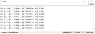
After compiling and uploading the code, select “Tools → Serial Monitor” in the Arduino IDE. You should see the motors running, the LEDs (on the breadboard and the ULN2003 boards) blinking. The response to pressing (and holding) / releasing the microswitches and turning the poti will be plotted to on the serial monitor window.
But: we are not finished yet, as the system only goes back and forth. So let’s do some theory next.
Step 3: Motion Theory
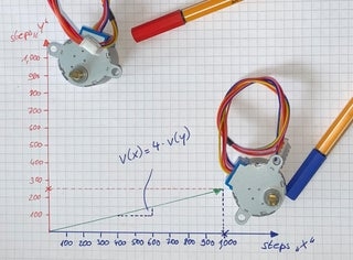
Consider we have two stepper motors called “x” and “y”. Both start at a position of 0 degrees. “x” wants move 1,000 steps, while “y” should only go for 250 steps. Together they should move at a speed of a maximum of 100 steps per second, and they are expected to stop at the same time.
Now, there are two major obstacles:
- If both steppers are starting with a speed of 100 steps per second, “y” will only need a quarter of the time of “x”. Consequently, we apply that “maximum demanded speed” only to “x” while we reduce the speed of “y” to 25 steps per second. Hence, after 10 seconds both axes will arrive simultaneously at their destination. Generalizing this case, we must
- always find the axis that has to travel more steps than the other, and then
- limit the speed of this axis by
speed(axis with more steps) =speed(defined by user) * steps(axis with less steps) /steps(axis with more steps).
- If we start both axis with their full speed as calculated in the previous step, the axis will be expected to move with this speed immediately which is impossible due to inertia and friction of the motor, of it’s integrated gears and of anything that is driven by the motor. Additionally, the 28BYJ-48 motors are not really powerful. Hence, they could easily lose steps if we start at full speed – or even worse, the integrated gears could be damaged if the load is to big, because they are made from plastic in the most cases. Thus, we should smoothly accelerate each motor in each motion. This can be easily achieved using the AccelStepper library as shown in the next step. For compensating resulting acceleration delays, we apply the formula above not only to the speed but also the acceleration value of each axis.
Step 4: Install the AccelStepper Library
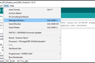
Within the Arduino IDE, go to “Tools → Manage Libraries…”. Browse for the AccelStepper library, select the latest version and hit “Install”. During the installation, the IDE may ask for other libraries that are needed to run the AccelStepper library. If so, just acknowledge to install these dependencies, too.
Step 5: “The User Interface” or “How Our ‘Machine’ Will Work”
The objective of our set-up is to move both motors from a given start position to a given end point synchronously. The AccelStepper library will provide a smooth acceleration – but what are the buttons for?
The buttons, the potentiometer and the LED provide a simple user interface.
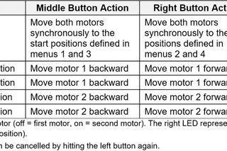
- The left button toggles through 5 “menus”. Each time you press it, the next “menu” will be activated. After the fifth menu, it will go back to the first one again.
- The middle and right buttons move the motors within these “menus”.
- The potentiometer sets the speed for the next movement.
Now, what are these “menus”? The table in the picture above gives an overview.
Using menus 1…4, you can move the single motors around. The start/end positions will be handled as follows:
- If you move the motors within menus 1 to 4, you will modify the corresponding start or end position
- If you do not move the motors within these menus but just toggle to the next menu using the left button, the stored positions will remain unchanged.
This entire concept might look confusing, but it gets much clearer once you will test it on the board with the code provided in the next step. As an outlook, the idea behind these menus is to replace the LEDs by a small TFT display, which is presented in an upcoming instructable.
Step 6: Make It Run – the Proper Code
Now compile the “Two_Steppers_-_Proper_Code.ino” file attached to this step. For details you may refer to the comments in the code, so I will just give a rough overview here.
- The setup() method initializes the stepper objects from the AccelStepper library and input/output pins of the Arduino.
- The loop() method manages the “menus”:
- In the (initially set) menu 0, it makes the LEDs flashing and waits for either a switch to menu 1 (left button) or the start of a forward (middle button) or backward (right button) by calling the executeMotion() method. Just after power-up, calling this method will have no effect, because start and end positions are all set to 0. Hence, you must switch to the subsequent menus first.
- In all other menus, the main loop will call moveAxisManually() which provides single axis movements for defining the start and end positions for each motor.
- The executeMotion() method moves both motors synchronously applying the “theory” from step 3 of this instructable. During the movement, both LEDs will be switched on after which both motors will accelerate to their calculated speeds. By callingstepper[0]->run(); stepper[1]->run(); in a while() loop as fast as possible, the AccelStepper library is generating the required pulses to the ULN2003 boards. This process will go on until either the target position is reached or the left button is pressed for cancelling the motion. Please note that the speed can be only changed using the potentiometer before the motion is started.
- The executeMotion() method is used in menus 1…4 for moving the motors for- and backwards in order to set the start and end positions. As in executeMotion(), the stepper pulses are generated in a while loop which will be only left if the backward (middle) or forward button (right button) is released.
- The method waitUntilAllButtonsAreReleased() is called after each movement to make what it says: in order to avoid confusing button states, it waits until the user releases all buttons before the next interaction can be started.
Step 7: Final Test and Applications
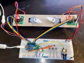
A demonstration of the completed “machine” is shown in the video on top of this tutorial where one motor goes for three quarters of a rotation while the other one travels only one quarter rotation. You can recreate this “machine” using the attached mask. Simply print it, glue it to some cardboard, cut at the marked seams and use duct tape to fix the ULN2003 boards and the motors to it. As a last step, cut-out the arrows and stick/glue them to the motor shafts.
You are now able to move the two steppers synchronously to a target position. A follow-up tutorial will show how to make the “machine” portable, add a TFT screen and a proper housing, and how to feed it by a single power source. In a third tutorial, this device will be used as a control unit for an ultra-low-cost, light-weight 2-axis GoPro/smartphone slider.
Source: Synchronized 2-Axis Motion With Variable Speed (Arduino + LEDs + 28BYJ-48)
- How are the motors powered safely without using USB?
The motors are powered by a separate 5V power supply connected to the plus/ground rails and the ULN2003 boards, with a bridge between both ground rails; the Arduino can be USB powered for tests. - Can this run without additional Arduino libraries?
The initial first test sketch runs without additional libraries, but AccelStepper is installed for smooth acceleration in the proper code. - What pins connect the Arduino to the ULN2003 boards?
Motor 1 uses D2 to D5 to In1-In4 of its ULN2003; motor 2 uses D6 to D9 to In1-In4 of its ULN2003. - How does the system ensure both axes stop simultaneously?
The axis with more steps has its speed and acceleration reduced proportionally so both axes complete motion at the same time as described in the motion theory formula. - Does the project include acceleration handling?
Yes; the AccelStepper library is used to provide smooth acceleration and acceleration values are scaled per the synchronization formula. - What is the purpose of the three microswitches and potentiometer?
The left button toggles five menus; the middle and right buttons move motors within menus; the potentiometer sets the speed for the next movement. - How are LEDs used in the system?
Two LEDs indicate menu/activity states; during executeMotion both LEDs are switched on while motors accelerate to calculated speeds. - How are button debouncing or stuck states avoided?
The code calls waitUntilAllButtonsAreReleased after movements to ensure all buttons are released before the next interaction.