Summary of Stripboard Arduino shield for programming ATtiny45 and ATtiny85
This article details the construction of a custom stripboard Arduino shield designed to program ATtiny45 and ATtiny85 microcontrollers. By replacing temporary breadboard setups with a permanent, soldered circuit, users can efficiently flash chips using an Arduino as a programmer. The guide covers preparing headers, cutting stripboard tracks, and soldering components to create a durable tool for high-volume chip programming.
Parts used in the Stripboard Arduino Shield:
- Stripboard (14 rows by 23 holes)
- Single core wire
- Two 4-pin female headers
- One 8-pin IC socket
- One 10uf capacitor
- One 8-pin male header strip
- One 6-pin male header strip
- ATtiny45 or ATtiny85 chips
- An LED
This instructable (entered in the Arduino Challenge contest – you can vote for it above) shows how to make a stripboard Arduino shield for programming either ATtiny45 or ATtiny85 microcontrollers with an Arduino, as per these tutorials from the High-Low Tech group at MIT:
Arduino board as ATtiny programmer
Programming an ATtiny w/ Arduino 1.0
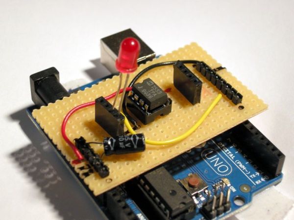
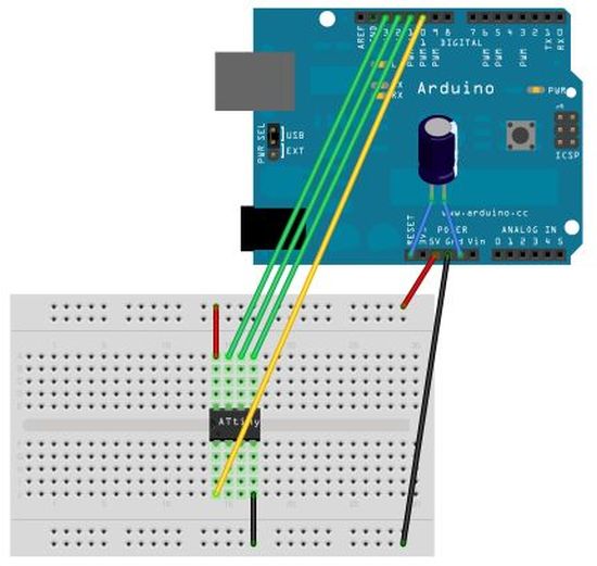
The top link shows a breadboard arrangement for the programming set-up, but if you’re working with lots of chips it’s neater to do away with all those wires and just have something you can plug in to use when needed!
You will need to follow the instructions at the first link in order to configure both your Arduino programming environment and your Arduino board to be able to use this shield. It’s worth working through the breadboard version before tackling this, so you know everything else is working as it should…
To make this shield, you will need:
* Some stripboard (I’m using a piece with 14 rows and 23 holes)
* A few lengths of wire (I’m using single core)
* 2 x pieces of female headers, with 4 pins/holes
* 1 x socket for an 8-pin IC chip
* 1 x 10uf capacitor
* 1 x 8 pin length of male headers
* 1 x 6 pin length of male headers
* ATtiny45 and/or ATtiny85 chips to programme
* An LED to check the blink sketch has uploaded correctly
* Soldering equipment
* Pliers
* A well-lit working environment – helps to avoid having to do the soldering again in the morning *ahem*
* Some permanent markers might be useful
* A track-cutting tool, a drill bit or a sharp knife
Step 1: Prepare the stripboard and the headers
Stripboard
First make sure you have an appropriately-sized piece of stripboard.
Is doesn’t really matter what size it is, so long as it is big enough to straddle the Arduino board with at least a few holes either side (soldering right to the edge has a tendency to cause the copper stips to lift up and detach from the stripboard). The main thing to look out for is to make sure the copper strips go in the right direction – they should be going across the board rather than along its length.
Headers
The next thing we need to do is prepare the 8-pin strip of male headers to accommodate the offset spacing on the Arduino board (you may skip this step if you’re using a clone board that already corrects this).
Follow the relevant instructions from this instructable – http://www.instructables.com/id/Embarassingly-Easy-Arduino-ProtoShield/ – to angle the pins. You will also need to push the pins down so they are level with the top of the plastic so that you have enough length underneath to make a good connection with the Arduino board.
Check they all work together
Place both sets of headers in the stripboard and check it all fits comfortably into your Arduino board. Make sure nothing fouls against the USB socket or anything like that.
I found the adjusted headers worked best with the off-set to the right as you look at them from their side of the stripboard.
Step 2: Solder in the male headers
Once you’re happy everything fits together as it should, go ahead and solder in the headers.
Keep your soldering as neat as you can and try not to get any solder further up the pins than you need to as this will make it difficult to insert them into the sockets on the Arduino board.
The 6-pin header is reasonably easy, but you may find the 8-pin header more tricky if the adjustment process has left the pins a little loose (I had a few that were prone to falling out!). To help keep the pins lined up, I used a second piece of stripboard as a spacer jig. (If you do this, place the pins in the top row of holes, not a few rows down like in my photo. This will make it easier to get access with the soldering iron…)
When the soldering is done, go back and check everything fits into the Arduino board again.
For more detail: Stripboard Arduino shield for programming ATtiny45 and ATtiny85
- What is the primary purpose of this project?
To create a stripboard Arduino shield for programming ATtiny45 or ATtiny85 microcontrollers. - Can I use any size stripboard for this shield?
The size does not matter as long as it is big enough to straddle the Arduino board with a few holes on either side. - How should the copper strips be oriented on the stripboard?
The copper strips should go across the board rather than along its length. - Why do I need to adjust the 8-pin male headers?
To accommodate the offset spacing found on the Arduino board. - What tool can help keep pins lined up during soldering?
A second piece of stripboard can be used as a spacer jig. - Where should the pins be placed if using a spacer jig?
Pins should be placed in the top row of holes to make it easier to access them with the soldering iron. - Does this project replace the need for a breadboard setup?
Yes, it provides a neater alternative to working with lots of wires on a breadboard. - What safety tip is given regarding the working environment?
A well-lit working environment helps avoid having to redo soldering work later.