Recently I’ve been posting a lot of projects that use an 8 bit resistor ladder digital to analog converter(DAC) and an Arduino to make sound. (see the Arduino vocal effects box, the Arduino drum sampler, and my audio output tutorial). The technique I’ve been using to make these DACs is very simple, it requires only a handful of 10k and 20k resistors wired together into a network. But the convenience comes with a price, as these DACs end up a little noisier than I would like at times. So I decided to buy a specialized IC that will be compatible with all the code I’ve already written for the resistor ladder DACs, but uses highly matched resistors to reduce noise. When I looked on Digikey for such a DAC, I found the TLC7528, a dual output 8 bit DAC IC. The dual output capability of the chip interested me a lot; while it is easy to set this chip up with one permanent output, it also gives you the option of toggling between two isolated output pins, making it fairly straightforward to set up a 2 channel audio output with a relatively small amount of additional effort/hardware setup/Arduino data pins.
In this instructable I’ll show you how to use the TLC7528 with the Arduino to output stereo audio. Stereo audio means 2 independent channels of audio. Stereo audio is especially fun when sent to headphones because you can achieve some interesting auditory effects since each ear is hearing its own independent channel of sound, some ideas include:
“3D audio” spatial effects– by adjusting the filtering, amplitude, and phase of two channels of audio you can simulate the experience of sound directionality, making a sound source seem to originate from a precise location in the space around you, here’s a great example
binaural beats– by sending two sine waves of similar -but unequal- frequencies to headphones (one to each ear), you will hear a pulsating beatnote that is thought to induce relaxation and other meditative effects. Here‘s an example.
panning– change the relative amplitude of a sound source in each channel of the stereo mix. This effect is simple, but can be really cool sounding, a great example is in the bridge of Led Zeppelin’s Whole Lotta Love (listen to it with headphones!)
Parts List:
(x1) TLC7528 Digikey 296-1871-5-ND
(x1) Arduino Uno Sparkfun DEV-11021
Other Materials:
22 gauge jumper wire
oscillosope
Step 1: 8 bit DACs and Serial vs Parallel
The TLC7528 is a type digital to analog converter (DAC). It takes digital data (numbers between 0 and 255) and outputs a voltage between 0 and whatever voltage you supply the chip with. The output voltage of the DAC can be calculated according to the following equation:
output voltage from 8 bit DAC = (supply voltage) * (digital input data) / 255
In this Instructable, I’ll be powering the DAC from the Arduino’s built in 5V supply, so the equation above can be simplified to:
output voltage from 8 bit DAC = 5V * (digital input data) / 255
From this equation, we can see that the TLC7528 would output 5V if it receives a value of 255, 0V if it receives a value of 0, 2.5V if it receives a value of 127, and so on. You may be wondering where the 255 came from, this is a result of the TLC7528 being an 8 bit DAC. 8 bit means that the binary numbers we can send to the DAC must have no more than 8 digits in them. In binary, numbers that are represented with 8 digits (or less) range in value from 0 to 255 (as opposed to the regular decimal numeral system where and 8 digit numbers range from 0 to 99999999). So there are 256 possible values (0-255) that the 8 bit DAC can receive. This can be calculated quickly from the equation below:
2^8 = 256 possible values
If we were using a 10 bit DAC, then it could receive 2^10 = 1024 different values, ranging from 0-1023. This means a 10 bit DAC has a higher resolution than an 8 bit DAC. Despite this, I’ve found that 8 bit DAC’s are generally much more useful than 10 bit DACs because data is easier to store and output from the Arduino in 8 bit form than in 10 bit form. For example, the data type byte in the Arduino language is for storing 8 bit numbers. If you wanted to store a 10 bit number, you would have to use an int data type, but int data types can store up to 16 bit numbers, so you would be wasting 6 bits of memory. Additionally, the pins of the Arduino are grouped together in clusters of 8 or less. On the Uno, the only full group of 8 are digital pins 0-7, this group is called PORTD. When writing Arduino code you can easily output 8 bits of data by setting the states of digital pins 0-7 all at once. In the code this is done by sending an 8 bit number to PORTD. For example:
PORTD = 255;
sets digital pins 0-7 HIGH, it is equivalent to the following:
digitalWrite(0,HIGH);
digitalWrite(1,HIGH);
digitalWrite(2,HIGH);
digitalWrite(3,HIGH);
digitalWrite(4,HIGH);
digitalWrite(5,HIGH);
digitalWrite(6,HIGH);
digitalWrite(7,HIGH);
but using the PORTD command sets all the pins simultaneously and is much faster. The following command would set digital pins 0-7 LOW:
PORTD = 0;
you can also use the PORTD command to set some of the pins high and others low. For example:
PORTD = 137;
137 in binary is 10001001, so sending 137 to PORTD will set pin 7 HIGH (because the first digit of the binary number is a “1”), pins 6-4 LOW (because the next 3 digits are “0”), pin 3 HIGH, pins 2 and 1 LOW, and pin 0 HIGH. You can read more about how this works on the Arduino website. You can even send binary numbers to PORTD, for example:
PORTD = B10001001;
is equivalent to PORTD = 137;
Finally, I’ll talk about how we get this data into the TLC7528. The TLC7528 is called a parallel DAC. This means that all the data we send to the DAC is sent in parallel. 8 bit parallel DACs have eight data connections between the Arduino and DAC that send all 8 bits of data at the same time. The opposite of parallel is serial, in serial setups you use fewer data connections (usually three), but send only one bit over at a time. So, in order to transmit an 8 bit number via a serial connection you have to send eight 1 bit packages, one after the other, while in parallel setups you can send all 8 bits at the same time. This means that serial connections require faster data transfer than parallel connections. If you are not worried about using 8 digital pins of the Arduino, a parallel 8 bit DAC is a good option because it requires less clock speed and is simpler to code.
Step 2: TLC7528 Overview
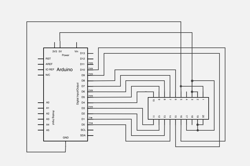
The pin diagram shown above comes directly from the datasheet of the TLC7528 DAC. As I described in the last step, the TLC7528 has 8 parallel data inputs, labelled DB0-DB7; these pins will connect directly to digital pins 0-7 of the Arduino. The TLC7528 is an interesting chip because it actually has two outputs on it (called DACA and DACB), which are both connected to the same 8 digital input pins. You can select which output to want to use by setting pin 6 HIGH or LOW (LOW outputs to DACA and high outputs to DACB). Pins 15 and 16 are used to control the outputs of the DAC as well, I’ll explain more in later steps.
Fig 2 shows a functional block diagram of the chip. Again, notice the data inputs, logic controls, and two separate outputs of the DAC. There are many ways to set up this DAC depending on what you are trying to do with it, you can read more about these on the TLC7528 datasheet. Fig 3 shows how to set up the DAC in voltage-mode operation. In this setup, the analog output of the DAC will be pins REFA and REFB, and the pins labeled OUTA and OUTB will be connected to a fixed input voltage (I used the 5V supply voltage). In the next step I’ll show you how I set this up on a breadboard.
(x1) Arduino Uno Sparkfun DEV-11021
Other Materials:
22 gauge jumper wire
oscillosope
For more detail: Stereo Audio with an Arduino