Summary of Starship X582 Incursion Starfighter Childrens Interactive Bed
This article details the transformation of a child's spaceship-themed bed into an interactive Starfighter cockpit. The project involved repurposing household items like dustbins and plant pots for structural components, reinforced with MDF and timber. Advanced electronics, including Arduino Mega 2560p boards, LEDs, speakers, and 3D-printed parts, created a functional flight console with touchscreen navigation, sound effects, and a remote-controlled self-destruct system.
Parts used in the Starship X582 Incursion Starfighter Childrens Interactive Bed:
- Mattress
- Two rectangular dustbins
- Cutlery holders
- Large plant pot
- Dirt sieve
- 18mm MDF
- CLS timber
- Poundland Bike pump
- Illuminated push buttons
- Arduino Mega 2560p
- MCP23017 chips
- MAX7219 chips
- Rotary buttons
- Toggle switches
- Keypads
- Text to speech recording
- LEDs
- Car speakers
- Old PC system with sub-woofer
- 2.4 inch touchscreen
- Joystick
- Motorised linear actuator
- Anti-trap sensors
- Four 2x40 LCD displays
- Arduino Pro Mini
- Mosfets
- Wav board MP3 module
- Bluetooth receiver
- Servo motor
- RGB LEDs
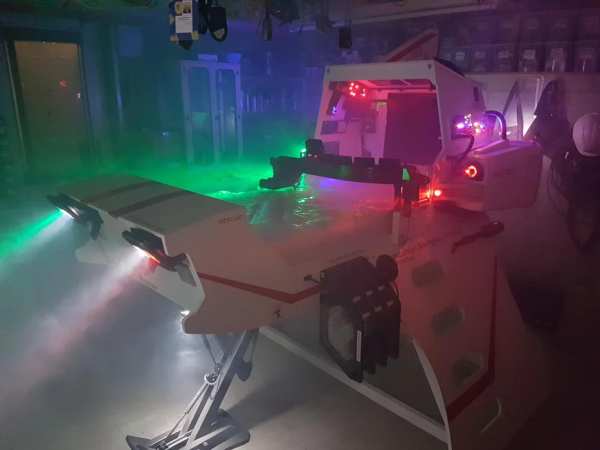
Now forgive my memory, as this was a few years back now. What started out as a children’s spaceship themed bed, turned into an epic build.
Supplies
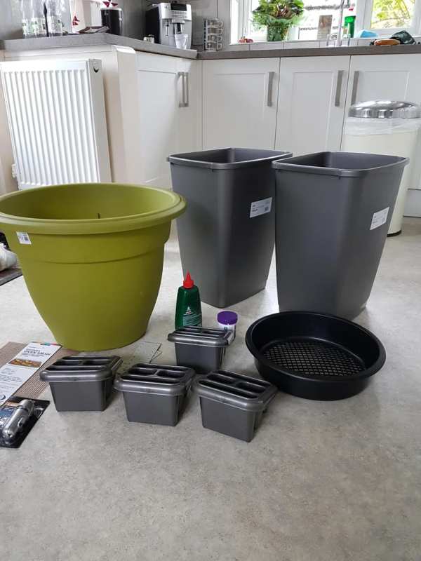
The project started with the purchase of a single mattress. I then walked around the local DIY store and started to find shapes that I thought I could make into Starship parts.
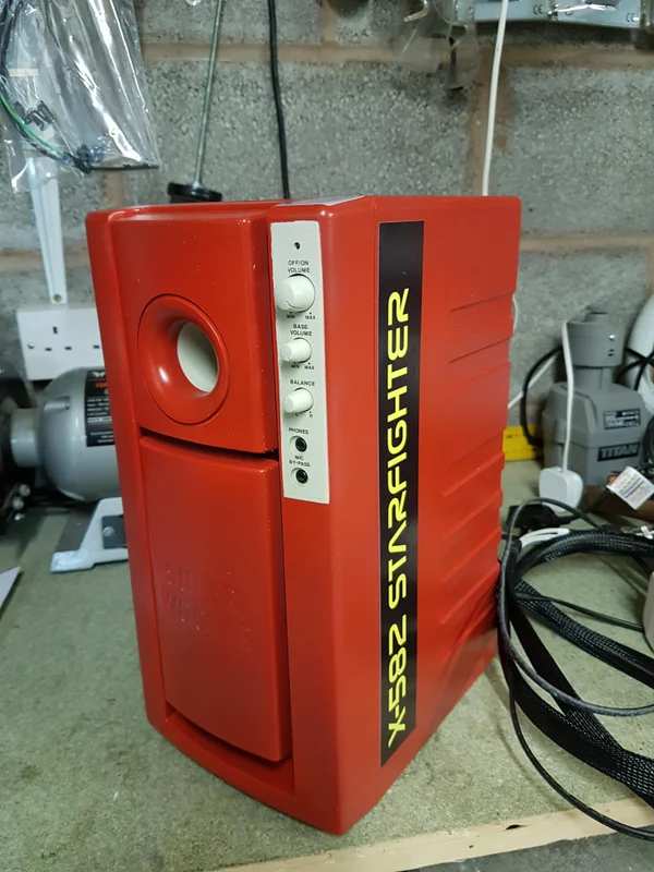
Two rectangular dustbins became the side Nacelle engine pods. Cutlery holders became the thruster pods, a large plant pot and a dirt sieve became the main centre engine.
All the framing was made with 18mm MDF and CLS timber. The front landing foot was made of scraps of timber, with a Poundland Bike pump as a hydraulic piston.
After designing all the parts, I then painted everything matt white.
Step 1: Assembly
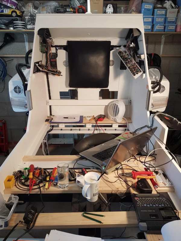
Well, what I can I say… months of design, assembly and fiddling followed.
The cabin lighting was a huge array of illuminated push buttons (thank you China). These and all the LED lighting were controlled by an Arduino Mega 2560p in the cockpit. The Mega controlled MCP23017’s to give me more inputs and outputs.
There was also an array of MAX7219’s controlling all of the illuminated buttons.
There were also rotary buttons, toggle switches and keypads.
The confirmation voice was a text to speech recording, put through an editor to add echo.
MILES of wiring went into this thing.
Plenty of the parts were 3d printed (far too many to list here). I basically made them up as I went.
The graphics were designed in Photoshop and simply printed out onto standard vinyl (Ebay). Very effective and cheap.
LEDS…. Loads of them. I just purchased a huge bag of mixed colours from China and placed them inside the engine pods, along with the car speakers.
The amplifier for the speaker system was actual an old PC system with a sub-woofer.
Step 2: Flight Console
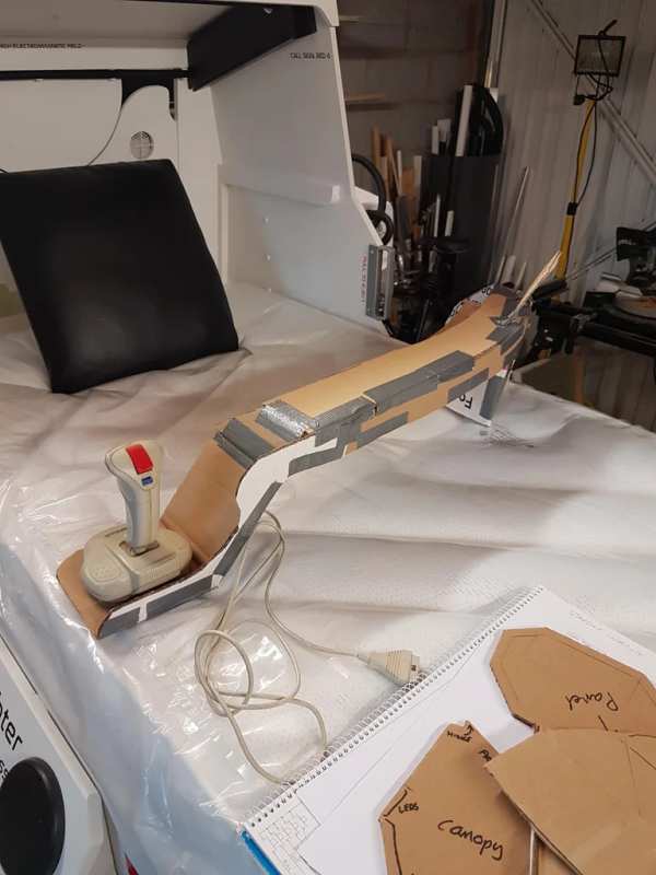
The console was mocked up in cardboard. I found an old joystick and a selection of old screens.
The main 2.4″ touchscreen allowed you to ‘fly’ around space. You could pick a planet to navigate to and then use the throttle and joystick to fly there.
It also showed your artificial horizon and weapons status.
The whole navigation ‘arm’ lifted on a motorised linear actuator with a whole host of anti-trap sensors to stop little fingers getting crushed.
The navigation console also had four 2×40 LCD displays (because I had them!). These showed all manner of information such as radio frequencies, speed, fuel, weapons etc
All this console ran off another Arduino Mega 2560p. This linked to the cabin Mega via serial.
Step 3: PSU
In the PSU lived an Arduino Pro Mini. This took care of all the sound effects and engine lighting.
Again, linked to the main cabin Mega via serial.
It contained a row of Mosfets to switch the various lighting effects, and two different MP3 modules.
One was a Wav board that supported over-laying tracks. This allowed me to ‘loop’ the engine sound seamlessly.
I could also increase and decrease the pitch of the engine.
All the interfaces and panels were breadboarded first to ensure they worked.
The other MP3 module was for the music. You could play various ‘space’ music themes and tunes in the cabin.
Step 4: Remote Control
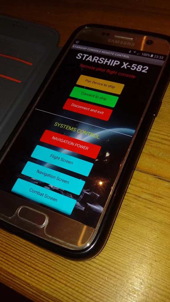
A Bluetooth receiver on the main cabin Arduino Mega allowed full remote control (and therefore parental control) of all the systems.
This was written using MIT App inventor 2.
Step 5: Self Destruct System
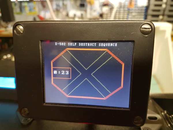
Lifted straight from the film Alien. I found an old control panel that I decided could be the self destruct system.
I added a servo to give it a ‘moving’ part and once armed, it announced the destruct system was armed with the associated countdown.
The navigation screen switched to a countdown timer (Alien style) and the cabin RGB LEDS pulsed amber/red.
Step 6: She’s Flight Ready
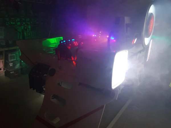
If you want to see a grown man wedged inside a child’s bed, then have a look below!
Source: Starship X582 Incursion Starfighter Childrens Interactive Bed
- What materials were used to frame the structure?
The framing was made with 18mm MDF and CLS timber. - How was the main engine constructed?
A large plant pot and a dirt sieve became the main centre engine. - Which microcontroller controls the cabin lighting?
An Arduino Mega 2560p located in the cockpit controls the lighting. - Can you navigate to different planets using the console?
Yes, the main 2.4 inch touchscreen allows you to pick a planet to navigate to. - How does the self-destruct system work?
A servo gives a moving part on an old control panel, triggering a countdown timer and pulsing RGB LEDs. - What software was used to create the remote control app?
The remote control was written using MIT App inventor 2. - How is the engine sound looped seamlessly?
A Wav board supported over-laying tracks to loop the engine sound. - Where were the graphics printed?
The graphics were designed in Photoshop and printed onto standard vinyl from Ebay.