Summary of Spotted Gecko Habitat Temperature Monitor/Thermostat W/Arduino & ESP8266 ESP12
Summary: Automated temperature monitoring and control for a spotted gecko enclosure using an ESP8266 NodeMCU, DS18B20 sensors, and a relay to switch an under-tank heat pad. The system hosts a web page showing temperatures and uses code-configured thresholds to toggle heat and lighting.
Parts used in the Spotted Gecko Habitat Temperature Monitor/Thermostat:
- ESP8266 ESP12 NodeMCU SOC
- Relay
- DS18B20 Temperature Sensor
- HeatPad (Under Tank Heatpad, UTH)
- NodeMCU Base
- Jumpers
- USB Micro Cable
- Modified extension cord (for relay to device connection)
Soooo….Wifey decided that it was time for a new pet. Spin the wheel….A Spotted Gecko!! Well, Geckos are apparently very temperature sensitive creatures so we invested in a UTH (Under Tank Heatpad) for those of us that are new to the world of reptiles. The purpose of said UTH is to provide warmth from below, to about 1/3rd of his enclosure…in this case a 10 gallon aquarium for the time being. The geckos like their bellies warm when they sleep from what I understand. This UTH only has ON/OFF and no temperature regulation. The thought of needing to check it every hour 24X7 and turning it on or off depending on his comfort wasn’t gonna happen (nothing personal Mr. Gecko but ‘been there done that’ with my own human babies 20 years ago, please no more)…sooooo…ENTER ARDUINO and ESP8266 (and a few other goodies)! Automation of the temperature monitoring and regulating, and hosting a web page to display the current temperature statuses to any internet browser. Mr. Leonardo Gecko is happy…as am I!
Step 1: What’s Needed

Substitute as needed for your individual requirements/parameters. Links to products are only for examples and not promotion. I did not use a resistor for the DS18B20. Please use your own judgement.
2. Relay
5. NodeMCU Base
Jumpers, USB Micro Cable
Step 2: Software Setup – Initial (Assuming Arduino IDE Is Already Installed)

We will also assume that you are familiar/comfortable with utilizing Arduino libraries.
All libraries should be available via github for free, if not already installed in your IDE.
You’ll be needing the following libraries/etc:
- OneWire.h OneWire Library Download
- DallasTemperature.h DS18B20 Library Download
- ESP8266WiFi.h (ESP8266 IDE Library)
- ESP8266WebServer.h (ESP8266 IDE Library)
- If you do not have the ESP8266 libraries…head over here for the full details and install steps: ESP8266 Core
- OneWire Address Finder 1 Wire Address Finder You will be needing this to determine the unique address of your DS18B20 sensor(s).
Step 3: Hardware Setup
For this section, the steps explained are based on my setup. Adjust as needed. DS18B20=sensor
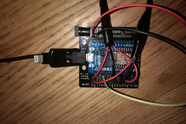
- Install NodeMCU board onto Node Base. (confirm the correct orientation by antenna locations matching on each or pin numbers matching if listed on base)
- Install female terminator connections on sensor(s). (I snipped, stripped, soldered and wrapped jumpers to the DS1820B’s lines)
- Attach Posi of both sensors to same 3.3v rail on Node Base. (Assuming 2 sensors are present. If only one, then connect just the one) See Pic.
- Attach Neg of both sensors to same ground rail on Node Base. (Assuming 2 sensors are present. If only one, then connect just the one) See Pic.
- Attach Data of both sensors to same pin D3 rail on Node Base. (Assuming 2 sensors are present. If only one, then connect just the one) See Pic.
- Identify the DS18B20(s) unique device address:
- Temporarily disconnect one of the sensors from the NodeMCU.
- Follow the steps provided here:DS18B20 Device Address Finder It looks like a lot of steps but really is rather quick and painless…and DEFINITELY necessary.
- Mark the current sensor in some manner (piece of tape, etc) for later identification to match to address.
- Power off your Node and repeat step 1 with additional sensor(s) is needed.
- Reconnect all sensors as described in initial steps above.
- Temporarily disconnect one of the sensors from the NodeMCU.
Step 4: Time to Check Some TEMPS!
- Assumptions/Pre-Req’s:
- You have obtained and installed all necessary libraries from the Software Setup step of this Instructable.
- You have obtained the unique device addresses(s) of the sensors from the Hardware Setup step.
- Make/Confirm all connections and power up your Node.
- Load the attached NODE_DS18B20_Gecko_WEB_SHARE_12Aug17.ino I have called out via OBNOXIOUS comments in the source…all of the fields that need changing.
- Modify the code with your unique specific details for the following at the least:
- Your Network SSID and SSID Password
- DS18B20 device address(s) obtained in previous step.
- TCP Port (default is 80, the code is set to 6969 at this time)
- COMPILE! (I usually start praying at this point for no errors).
- Load it to your Node.
- Open Serial monitor. With any luck you are seeing data here, hopefully with temperatures. Force a Temp. change on the sensor probe to see if it is in fact fluctuating.
- Take note of the field names being displayed and personalize the source accordingly.
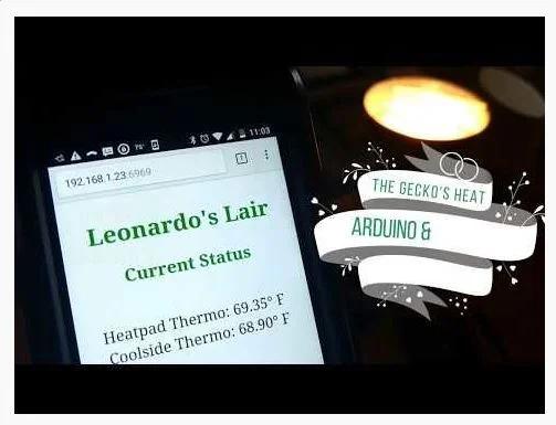
- Open a web browser to http://123.456.789.123:2017 (This was an example)
- EG – Mine loads with http://192.168.1.23:6969
- Take note of the field names being displayed and personalize the source accordingly.
- Modify the code with your unique specific details for the following at the least:
Step 5: It’s RELAY Time…SHOCKING!
See what I did there? Relay…Electricity…SHOCKING. OK…nevermind! Haaaaaaa
BE CAREFUL NOW. ELECTRICITY IS SERIOUS BUSINESS…NO KIDDING!
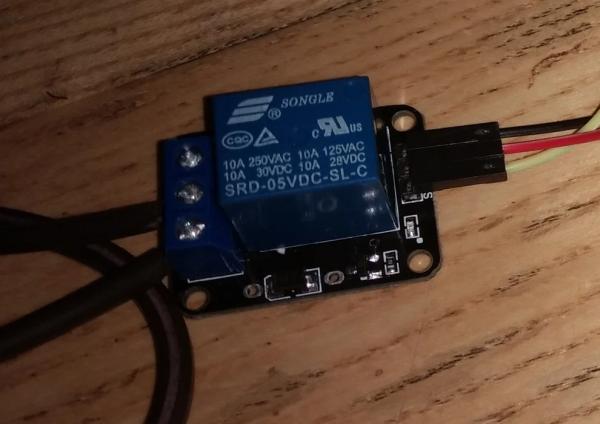
When I work with relays, I mod an extension cord instead of risking harm to the wires of the ‘device to be controlled’.
For detailed steps on that process, head here first. (Added “how-to bonus” included in video) How to safely mod extension cord to attach to relay.
- Depending on your project requirements, the power connection has 2 options on the relay, ‘Normal Open’ or ‘Normal Closed’. Consider your implementation for how to wire. “Will this only be turned on occasionally?” “Will it be on a lot?” “When do I want it to turn on or off?” etc…
- Modify your source code (IF statements in LOOP) with some high/low temperature thresholds.You may also need to change the logic depending on the relay wiring and your decisions. (Flipflopping the pin’s HIGH and LOW setting). Trial and Error…Experiment…that is half the fun in learning here. (Without hurting yourself or anyone/anything in the process of course)
- Modify the Relay Data pin assignment in source to match the physical connection. Mine is D8.
- Connect everything up and take your project for a spin!!
- Relay Posi to Node 5v.
- Relay Neg to Node Ground
- Relay Data to Node D8. (Or your data pin)
- In my specific case, we have the relay connected to a UTH (UnderTank Heatpad) for our Gecko. One of the DS18B20 sensors is securely/safely laid flat against the substrate inside his enclosure. The Arduino logic is set for the UTH to turn off if temp>94 and turn on if temp<88. The second sensor is on the opposite side of the enclosure suspended/dangling to simply report air temp. We will attach the Hoodlight RED bulb to a second relay to turn on if air temp<70 and turn off if air temp>78.
Source: Spotted Gecko Habitat Temperature Monitor/Thermostat W/Arduino & ESP8266 ESP12
- What is the purpose of the UTH in the project?
The UTH provides belly-warming heat to about one third of the gecko enclosure. - Can the system host a web page to display temperatures?
Yes, the ESP8266 hosts a web page showing current temperature statuses. - How are temperature thresholds controlled?
Thresholds are set in the Arduino source code IF statements to turn the relay on or off at specified temperatures. - What sensors are used to measure temperature?
DS18B20 temperature sensors are used, with one placed against the substrate and another for air temperature. - How is the relay wired to the NodeMCU?
Relay positive to Node 5V, relay ground to Node ground, and relay data to a Node data pin (example D8). - Do I need to find the DS18B20 device address?
Yes, you must determine each DS18B20 unique device address using a OneWire address finder and enter it in the code. - What libraries are required in the Arduino IDE?
OneWire, DallasTemperature, ESP8266WiFi, and ESP8266WebServer libraries are required. - How do I personalize the uploaded code?
Modify network SSID and password, DS18B20 addresses, TCP port, relay pin assignment, and temperature threshold values in the provided INO file. - Is it safe to modify the heatpad power connection?
The article advises caution and recommends modifying an extension cord for relay control and following safety instructions when working with mains power.