Summary of Spatial Synthesizer Kravox! Wireless, Motion- & Touch-Sensing
Kravox is an open-source, cross-platform digital musical instrument designed to mimic the tactile feel of mechanical instruments. It comprises wireless controllers that track motion and touch, a receiver unit, and Pure Data software for sound generation. This project enables users to build their own controllers using accessible components like Arduino Nanos, gyroscopes, and touch sensors, housed in customizable cardboard enclosures.
Parts used in the Kravox:
- 50*24 hole Perfboard
- 40-Pin female headers
- 40-Pin male headers
- 10 kilo-Ohm potentiometers and Knobs
- Blue 5mm standard LEDs
- 150 Ohm resistors
- 10 micro-farad capacitors
- 100 nano-farad capacitors
- NRF24L01 radio transceivers
- Arduino nanos
- 220 Ohm resistors
- MPR121 touch sensor boards
- GY-521 MPU 6050 digital gyroscope
- USB-A to USB-C cables
- Copper tape
- Powerbank
- Wire in many colors
- Shrinktube
A New Kind of Instrument
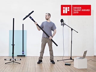
I invented Kravox during a research project at Lund University (Sweden) with the aim to give digital musical instrument controllers the feeling of conventional, mechanical instruments. Now I want to make Kravox accessible as a musical experimentation platform for everyone, so I created this detailed Instructable to enable as many people as possible to use this exciting new instrument!
How to Play Kravox
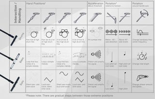
Playing Kravox is as quite straightforward. Just imagine you are playing around with an ordinary object like a broom and the way you touch and move it through space controls how sound is generated. See and hear how to play Kravox in this video.
Step 1: What Is Kravox?
Kravox is a cross-platform compatible, open source digital musical instrument that consists of three components – controller/s, receiver and software.
Controller/s
Up to three wireless controller devices can be connected. Each controller processes orientation- and acceleration data from a digital MPU-6050 gyroscope and touch data from two MPR121 touch sensor boards connected to an Arduino Nano. The controller/s send/s the data to a receiver device via nRF24L01 radio transceiver/s. If more than one controller shall be used, the second and third controller need to get individual addresses assigned. For more information about assigning the address see the info in the DECLARATIONS / NRF24L01 section of the controller code.
Receiver
The receiver passes the data received from the controller/s on via USB to a connected computer, together with data collected from several potentiometers. The provided receiver device code allows communication with up to three controllers, but will also work with only one or two without adjustments.
Software
The data from the receiver is processed in a programme written in Pure Data Vanilla that outputs sound.
Step 2: What We Will Build (incl. Video Tutorial!)
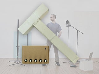
The beauty of Kravox is that it’s shape, how it sounds and how it’s played can be adjusted. This gave me the opportunity to design an easy-to-replicate Kravox version for this tutorial. Both the video above and this Instructable will show you all necessary steps of how to build fully functional controllers and a receiver from easily available electric components and cardboard.
(In case you are curious: On my youtube-channel you can also find a timelapse of how I made the larger version of Kravox)
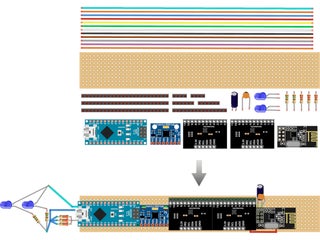
Step 3: Components
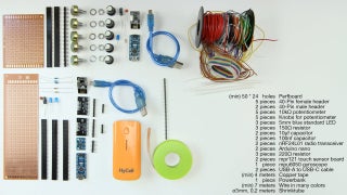
You will need the following components to build a Kravox controller + receiver station:
- {1x} 50*24 hole (minimum size) Perfboard,
- {5x} 40-Pin female headers,
- {5x} 40-Pin male headers,
- {5x} 10 kilo-Ohm potentiometers and Knobs for them,
- {3x} Blue 5mm standard LEDs,
- {3x} 150 Ohm resistors,
- {2x} 10 micro-farad capacitors,
- {2x} 100 nano-farad capacitors,
- {2x} NRF24L01 radio transceivers,
- {2x} Arduino nanos,
- {3x} 220 Ohm resistors,
- {2x} MPR121 touch sensor boards,
- {1x} GY-521 MPU 6050 digital gyroscope,
- {2x} USB-A to USB-C cables,
- {1x} 4 meters (minimum) of 1 cm wide copper tape,
- {1x} powerbank,
- {1x} 7 meters (minimum) wire in many colors and optionally
- {1x} 0, 2 meters of ø=3mm shrinktube.
Step 4: Tools
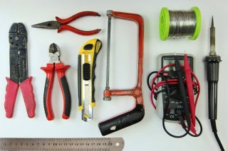
You need the tools in the picture to assemble the components:
- Wire Stripper
- Pliers
- Utlity knife
- Hacksaw
- Ruler
- Multimeter
- Soldering Iron + Solder
Step 5: Cardboard-enclosure Making Material and Tools
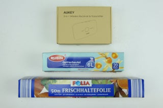
Later in the making process you also need some empty cardboard boxes or similar and glue, a glue gun, adhesive tape, one or more clamps and rubber bands to make the enclosures
Step 6: Making the Controller Board
Next I will explain how to make the controller electronics step by step from the parts mentioned above
If in doubt, where to solder in a cable, you can always come back to the circuit diagram and check, if the components will be connected right, once you attach the arduino and sensor-boards to the circuit board we are creating
Step 7: Making the Controller Board – Making the Circuit Board
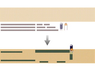
The first step is to cut the perfboard and female pin-headers to size
and assemble them together with a small and a big capacitor that help increasing the reliability of the radio-transceiver
- Cut the perfboard with a utility knife
- Cut the female pin headers with ahacksaw (I put them on a book to level them from the tabletop)
- Solder in the parts. You can already connect each pin-pair of the two
long female headers that sit next to each other. For the remaining headers it is enough to simply attach them with a little solder – preferably the pins that will have according to the circuit diagram no connection later anyway. When soldering in the capacitors, pay attention to the polarity of the electrolytic 10-micro-farad capacitor (the bigger one of the two). One side will have a stripe and usually also a shorter leg. That side needs to be connected to ground. The smaller 100nano-farad-capacitor is not polarized and can be soldered in either way
Source: Spatial Synthesizer Kravox! Wireless, Motion- & Touch-Sensing
- What is Kravox?
Kravox is a cross-platform compatible, open source digital musical instrument consisting of controller/s, receiver and software. - How does Kravox generate sound?
Sound is generated by processing orientation, acceleration, and touch data sent from controllers to a computer running Pure Data Vanilla software. - Can I use more than one controller with Kravox?
Yes, up to three wireless controller devices can be connected simultaneously. - What components process orientation and acceleration data?
A digital MPU-6050 gyroscope processes orientation and acceleration data within each controller. - How do controllers send data to the receiver?
Controllers send data to the receiver device via nRF24L01 radio transceivers. - What programming language is used for the software?
The data is processed in a programme written in Pure Data Vanilla that outputs sound. - How are multiple controllers distinguished from each other?
If more than one controller is used, the second and third controllers need individual addresses assigned. - What materials are recommended for the enclosure?
The tutorial suggests using empty cardboard boxes or similar items along with glue, a glue gun, adhesive tape, clamps, and rubber bands.